Opening the box. Inside you find a nice printed manual, a checked off parts list and 3 boxes. A long thin box contains the blades and tail boom. A big box contains the canopy with the mainmast assembly, chassis assembly and landing gear parts inside. The last box contains bags of parts all labeled.
Reading the manual, it explains to start with bag A and progress through the bags, not opening more than 2 at a time or you will get in a mess. All pretty straight forward so far, so lets get to it.
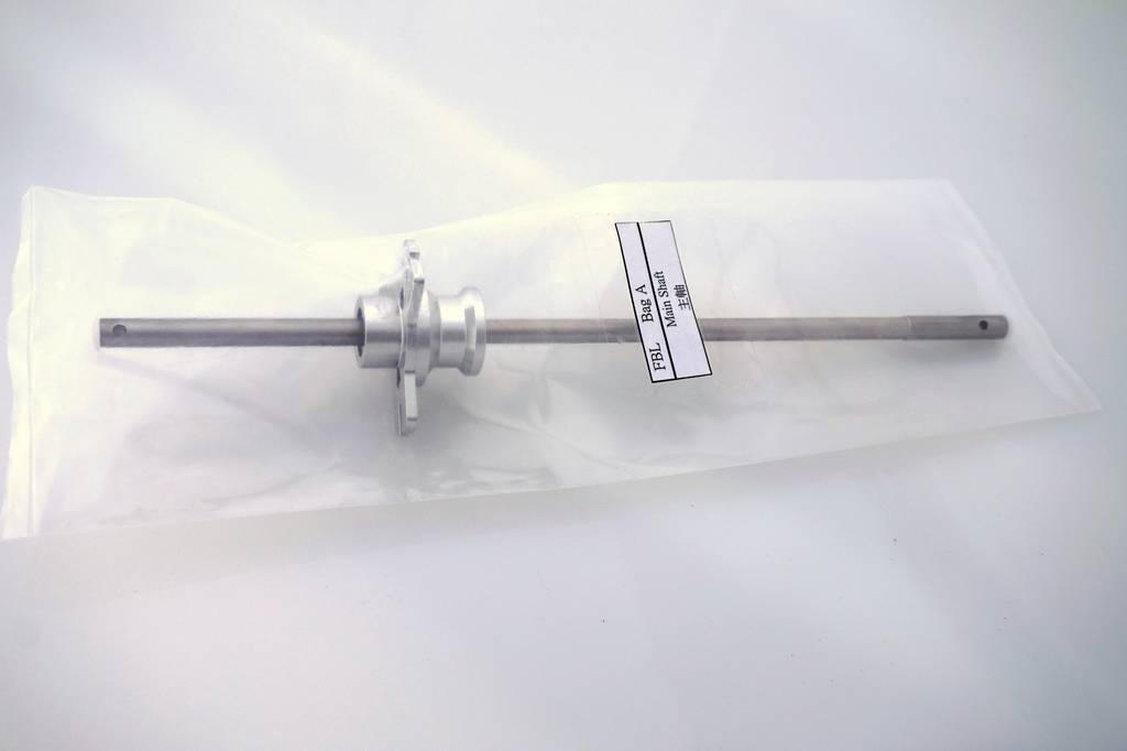
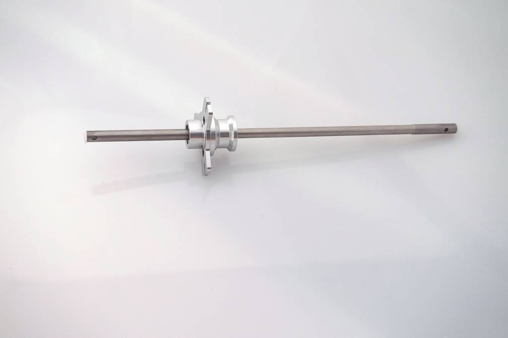
The first construction page shows the finished assembly that you are about to build. Then it tells you how to build it and which bags to use. So we start with bag A. This is what you get and opening the bag you find the item is fully assembled and a quick check shows the screws are loctited. Easy so far.
On to the next step, assemble the swashplate. Bag B
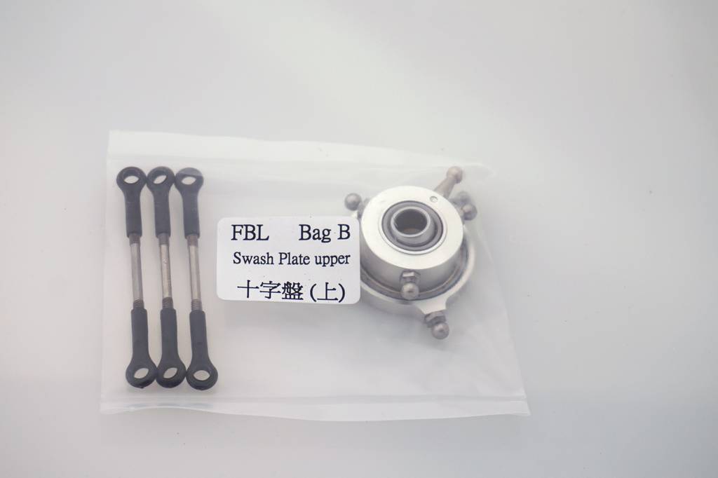
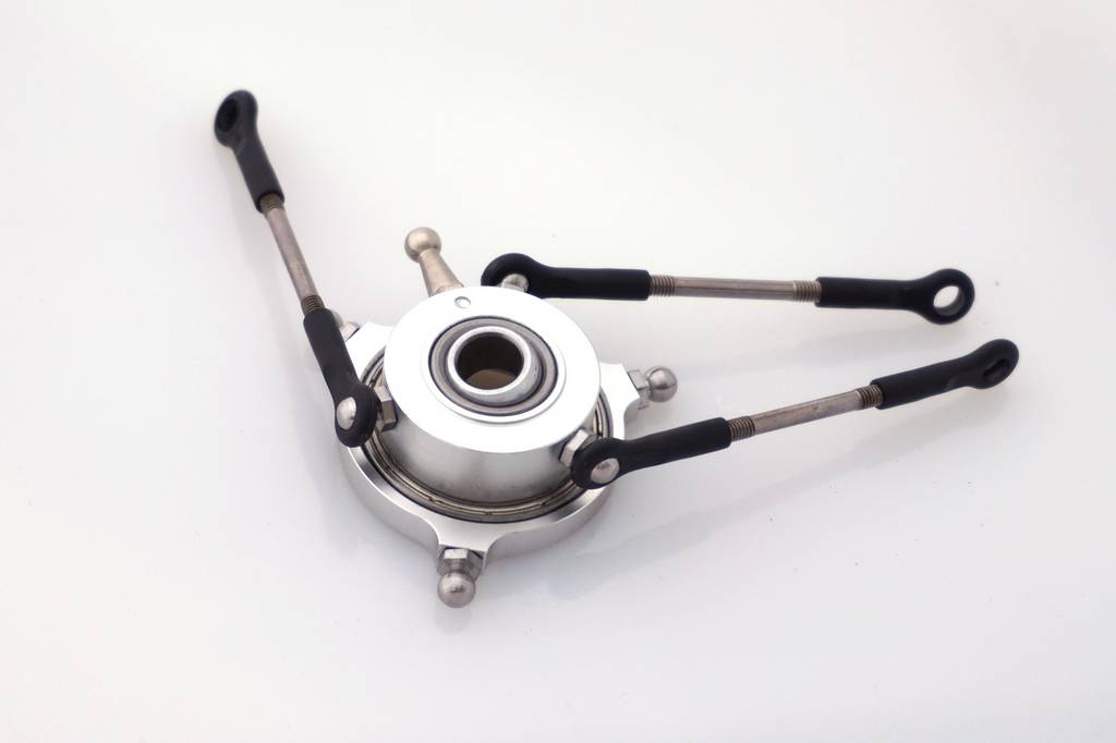
Push rods already with the ball links on, close to the required length. Final adjustment will be made when the assembly is complete. So, opening the bag and checking, all is good and everything that should be loctited is loctited.
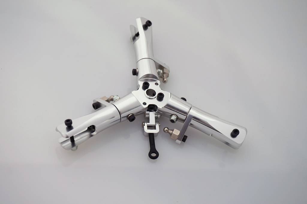
Now for the top rotor head, in bag C.
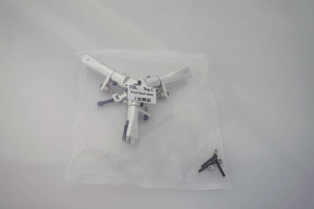
As you can see, it is fully assembled and taking one of the blade grips off shows the thrust bearing is greased and a quick check of the ball links shows they have loctite on them as well. Even the swash driver is assembled.
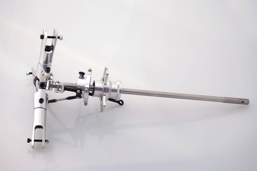
Take the plastic pushrod guide out of the center of the main mast. Slide the swashplate onto the main shaft, slacken off the 3 locking screws in the rotor head and slide that on. Now we get to use that bottle of loctite which has been sitting around. Remove the three 3mm cap head bolts from the head, apply loctite to the first one and screw it in looking through one of the other holes for one of the three locating holes in the top of the main shaft. Once the first screw is properly located, loctite and fit the other two 3mm bolts
OK, this bolt by bolt assembly is getting tedious, suffice to say, all the other main parts come out of their bags properly assembled
These parts go into the bottom rotor assembly and the manual is clear about how to assemble it.
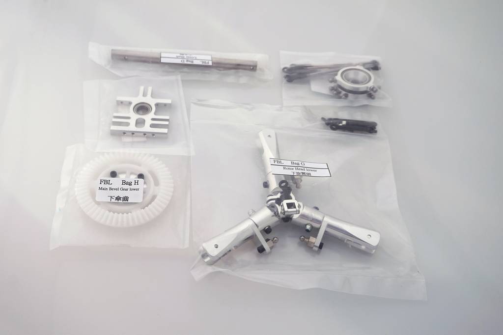
This is the lower rotor head assembled, and for the first time, you will have some parts left over after the assembly. There should be two 3mm cap bolts left, which we will use later.
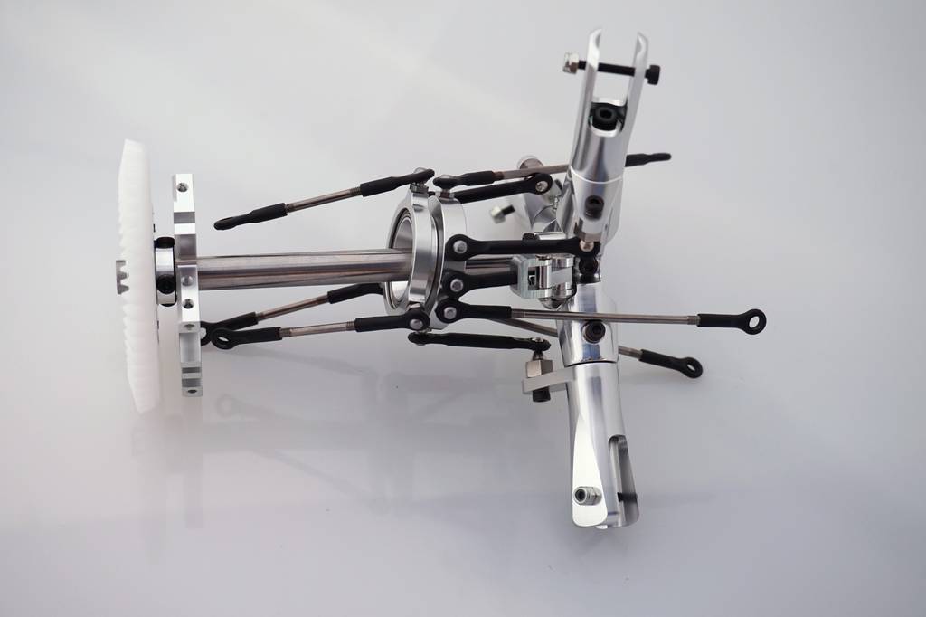
Now the top rotor head assembly is slid into the lower mainshaft I got a bit ahead of myself fitting the links from top to bottom, the guide needs to be bolted to the bottom rotor head first. There is a small projection on the bottom of the guide which fits into a locating hole in the top of the rotor head. Once it is in, the two 3mm bolts secure the two parts together,
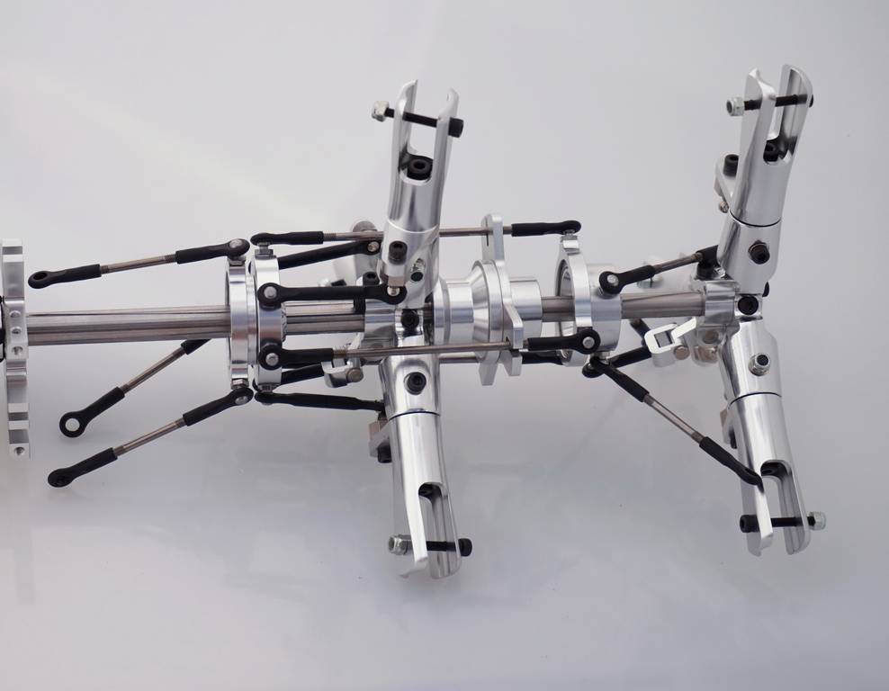
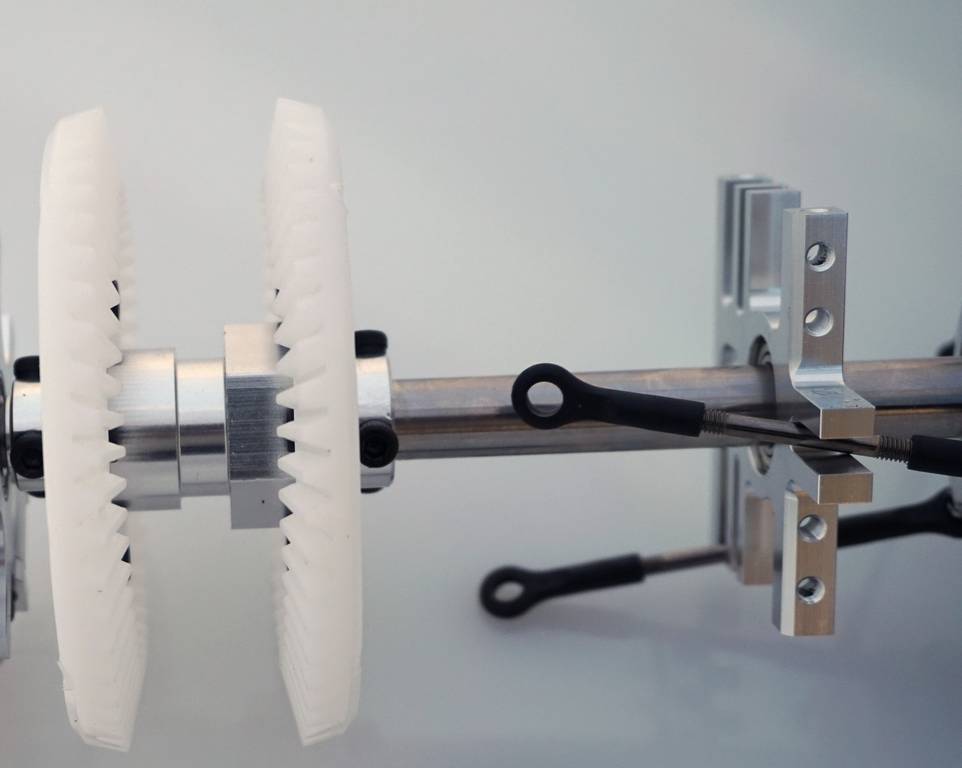
Next is simple. The aluminum bearing holder is slid onto the bottom of the lower mainshaft followed by the bottom gear. The three cap head bolts locate into 3 holes in the lower mainshaft.
Next we fit the yaw control mechanism. These are the parts we use.
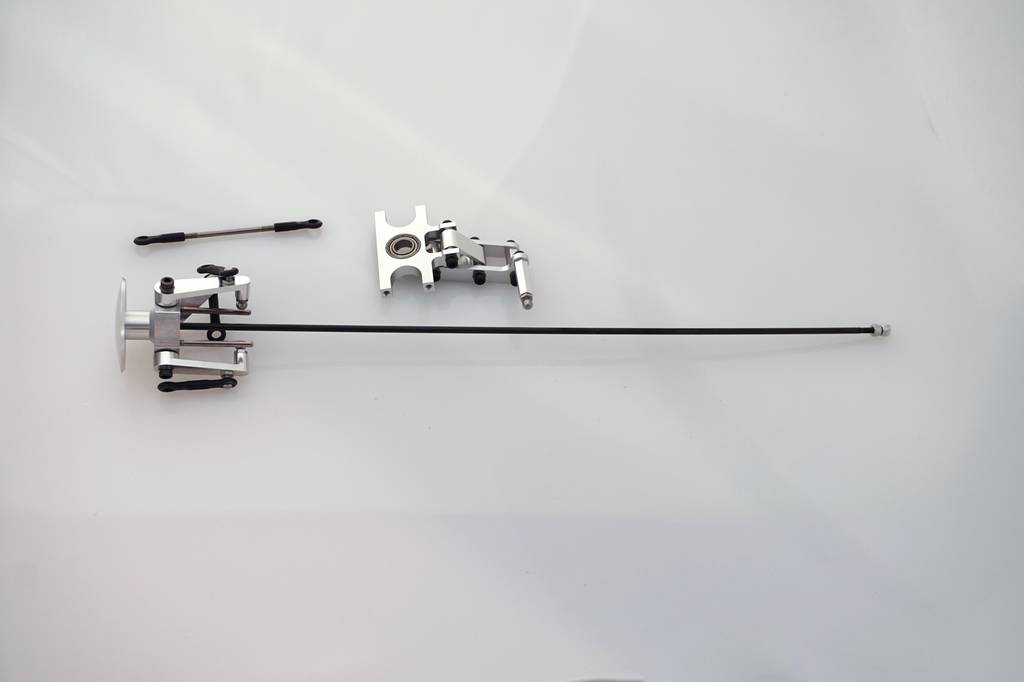
First thing to do is to remove the two locknuts from the bottom of the shaft.
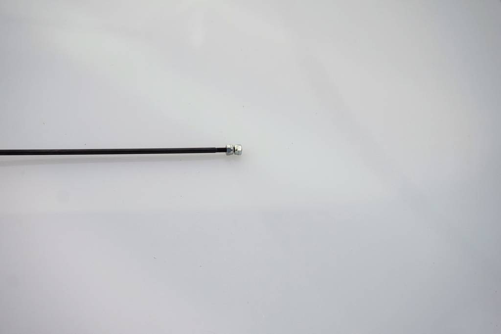
Then the bottom plastic rod guide is removed. The yaw control mechanism is slid over the bottom of the mainshaft, the plastic guide replaced and then one of the 3mm locknuts is replaced. Then the rod is fed through the yaw control unit and the other locknut is fitted. The top assembly has two pins which locate in the top rotor head and prevent it from turning. Now the links can be popped on.
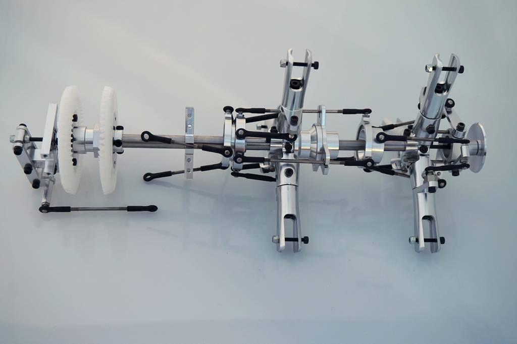
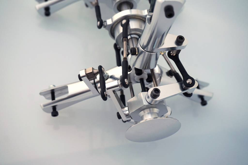
The next step in the manual is called final assembly! Opening these bags and assembling the whole mechanism took about an hour. Photographing it took 2 hours, I’m no photographer. I’ll cover the final assembly and the setup tomorrow.