
Vario Alouette 3 turbine
I ordered the Alouette 3 from Joe Howard some time ago. The kit arrived a month ago, but UPS had squished the main tub to a strange shape with lots of cracks in the glasswork. Fortunately, they paid up and a new one was shipped directly to me from Germany. ITS BIG!!!! I decided to get through the flying season, fix everything which was broken and put the Kamov to one side until the rest of the kit arrived.
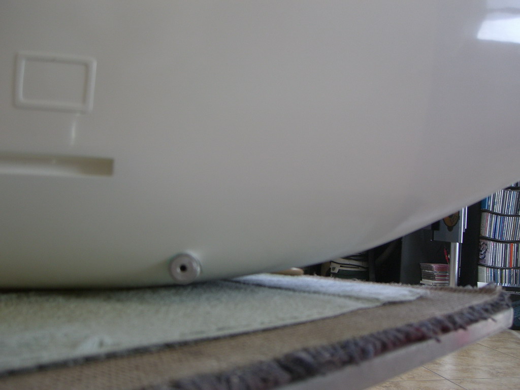
Thursday. The Alouette kit only had one set of instructions so I got started on them. I read the instructions carefully and then assembled this part
I had a heck of a time trying to figure out what it did. Finally it dawned on me. It's a remote extension to allow the tailboom to be removed. The gears unscrew it from the main tub!
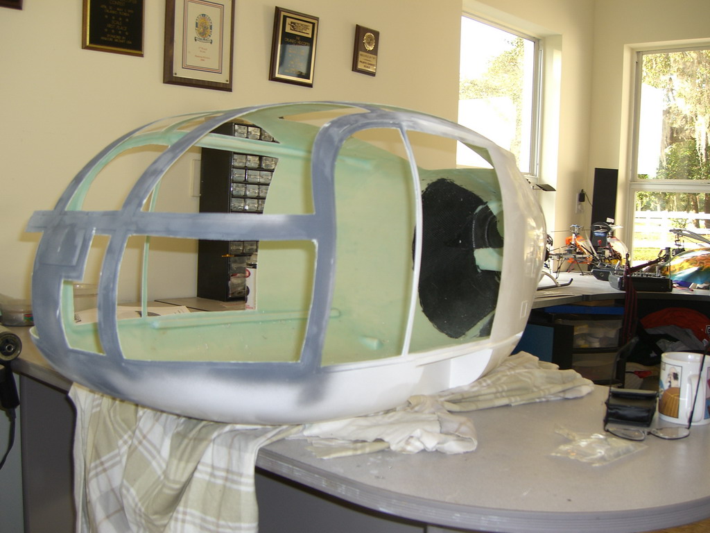
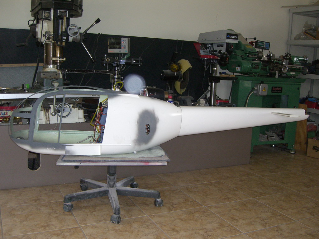
So, on to page 2. It said cut the holes out for the windows. The last thing in the instructions was cut and fit the windows. As usual, I decided to do it my way and cut the windows out first. There's a good reason for this. If you do it before you cut the holes, you have the stability of the complete fuselage. If you cut the holes, some of the frames are weak and bendy and things may not fit properly
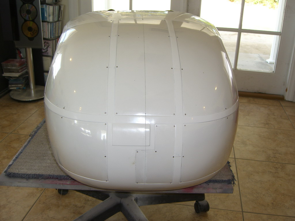
Next I still didn't cut the windows. I sanded down the seam, again, because I wanted the strength of the complete fuse to sand. Once the windows are cut out, its too easy to break something by pushing hard when sanding.
OK, now I cut the windows out! Curiously, Vario didn't mark out the hole for the rear doors, so I guessed where they should be and then cut them 1/4" smaller all round
Then I went and jumped in the pool! Apologies to those of you in the frozen north in places like Massachusetts, but it's 84 degrees here and the pool is at 90. Tomorrow, I'll get to finishing off the window holes with a file and some sandpaper.
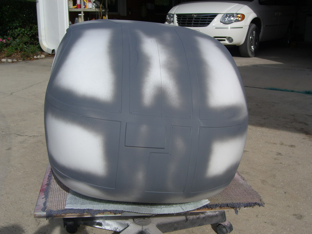
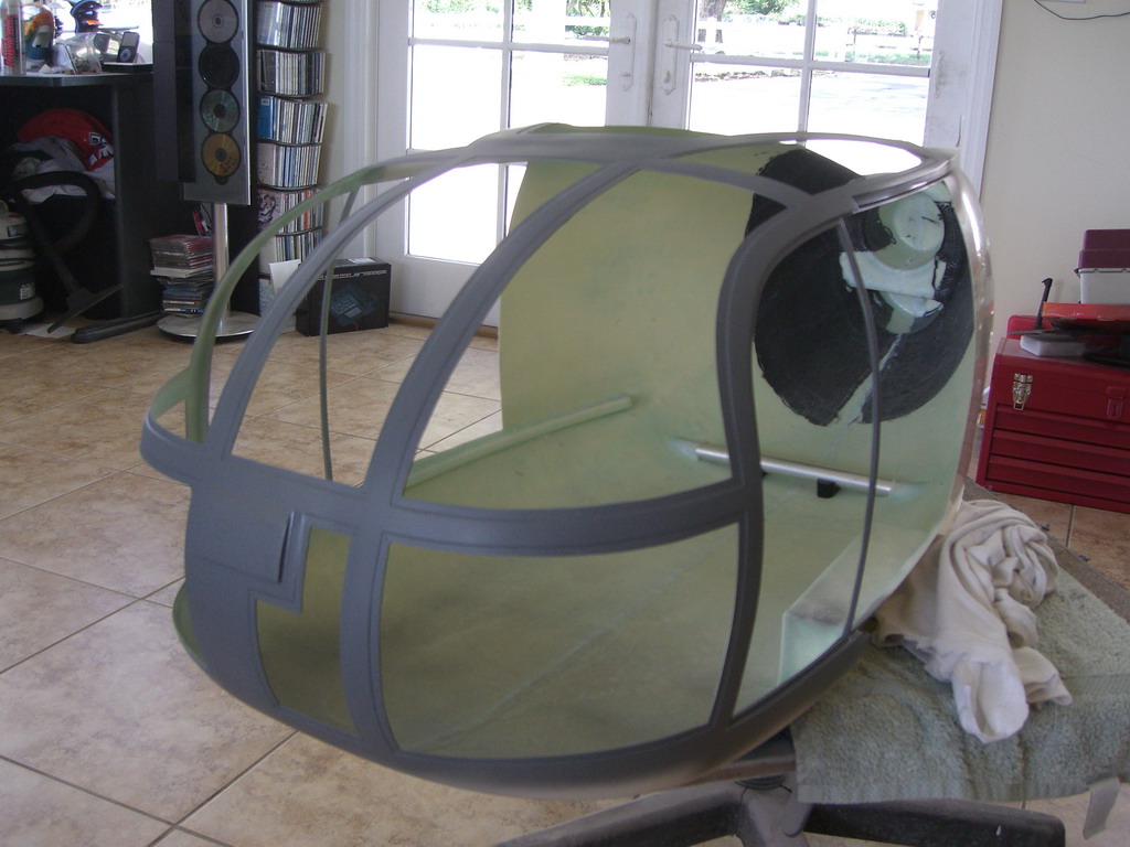
Well its Friday and I got started on tidying up the window holes. After I had them all straight and level, I gave it another coat of primer.
Then I fitted the bottom bar which has two functions. One is to attach the mechanics and wheels to the fuselage and the other is the bottom mount for the rear wheels. This just slid in. Well, after I had cut and trimmed the holes of course.
The mounting of the chassis through the bar and to the fuselage comes next and this locates the chassis in the tub. Unfortunately, I have a problem with the rear exhaust mount being too far back and after having a chat with Joe, I decided to make the mechanics set up and fit them into the chassis so that I could accurately cut the hole for the rear exhaust mount. So, I jumped in the pool again to wash off the fiberglass dust and then set about building the mechanics. I will continue this when they are done.
Wednesday. After a fun weekend building up the mechanics, it showed that the chassis had serious alignment problems. Discussions with Joe led to the analysis that I needed to do some modifications to the chassis by resoldering the position of two tubes. While I was at it, I elected to move the rear turbine mounting plate and the rear exhaust support to get them into perfect alignment. We did contact Vario in Germany and explained the problem. They showed us pictures on one from stock, which was correct so I guess mine was just a bad one. I cannot image that any others will get shipped out without being checked.
Anyway, that allowed me to put in the mounts for the chassis into the fuselage and drill the holes through the landing gear tube to support the rear. I used 24 hour Hysol for strength and tomorrow I get to take it all apart and fiddle with the rear alignment tubes. You will see what I mean tomorrow

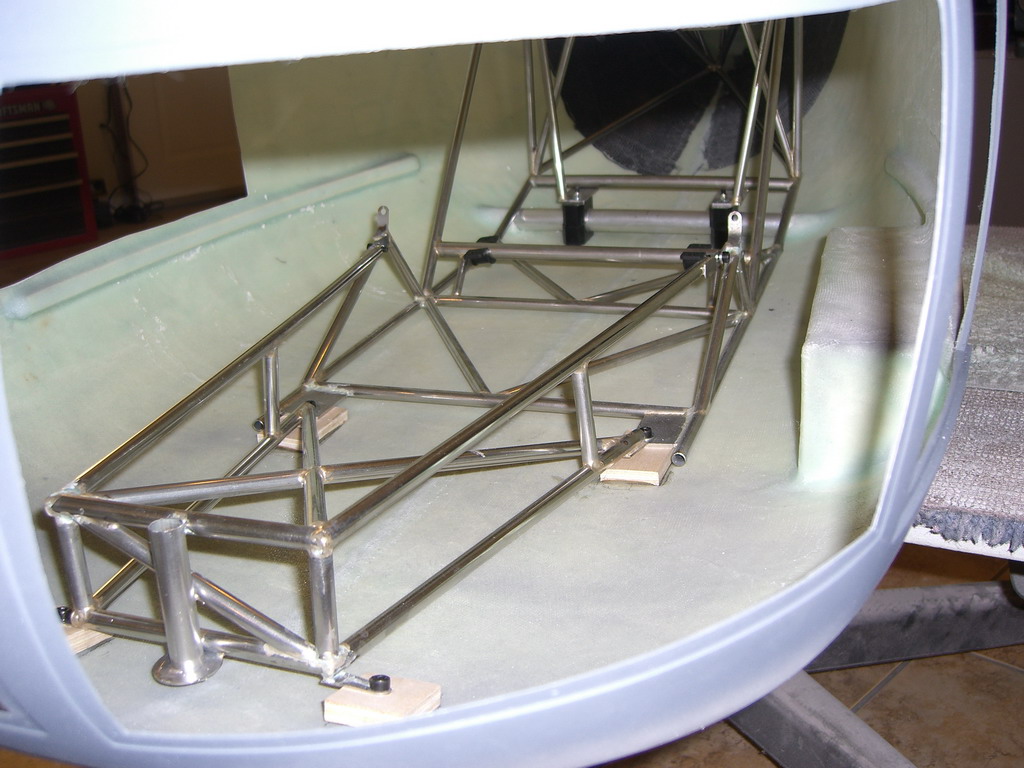
Friday. The tubes in the picture had to be bolted to the rear wall and then glued into position.
They had been fitted loosely and then when the chassis was in the correct position, they were tightened up. Then I removed the chassis, marked the position and then removed them and applied some 24 hr Hysol to the rear of the tube mounts. Reassembling it and fitting the chassis and it looks like this
Then I had to build up the rear wheel assemblies and mount them. Unfortunately Vario did not see fit to mark the position of the holes and so a little filling was necessary once I had them in the right place.
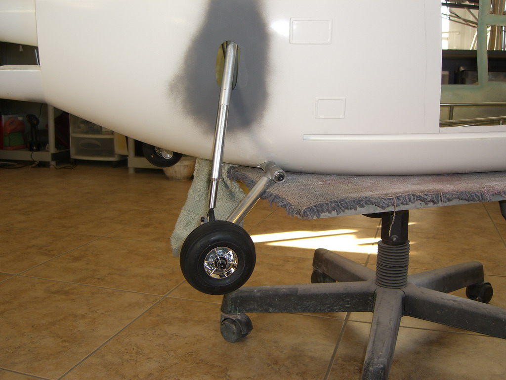
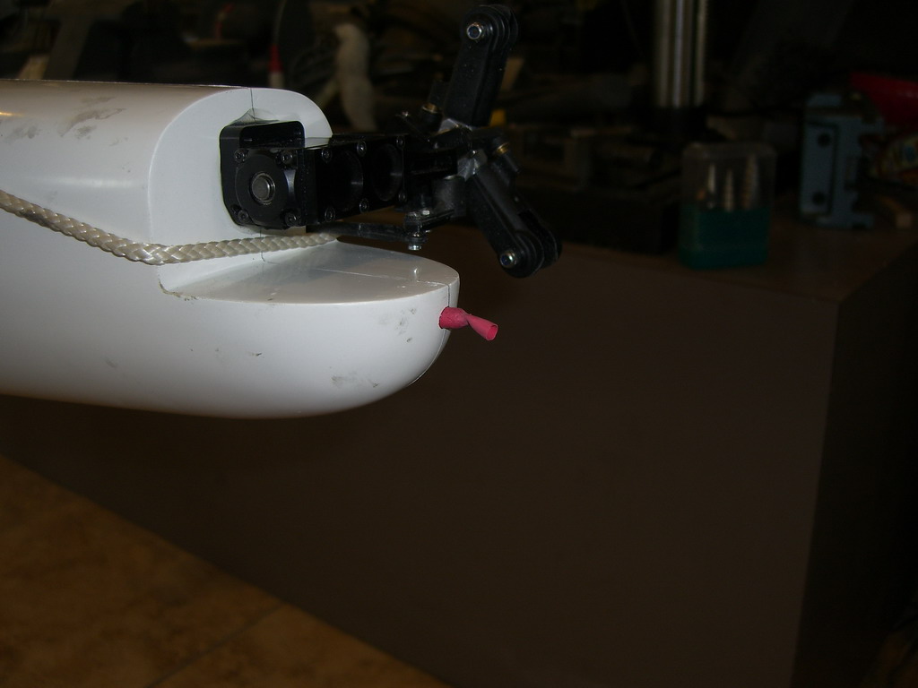
Then I did the front wheel
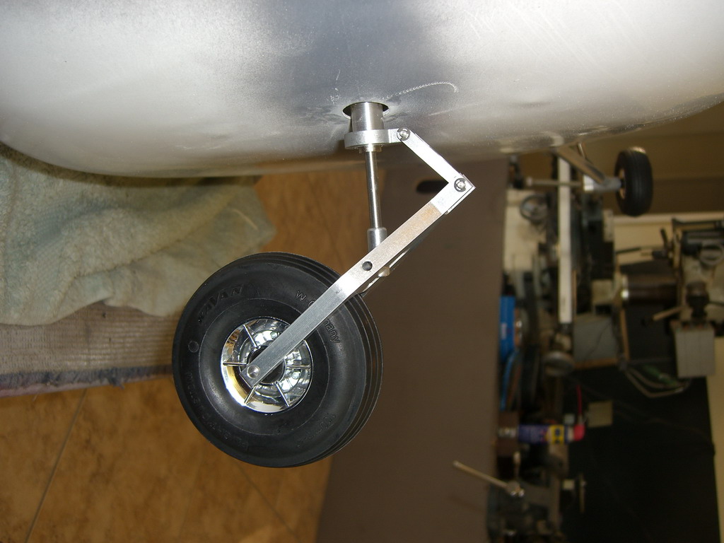
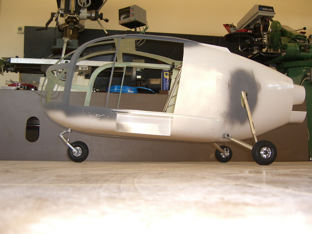
And here she is on all 3 wheels. They are all sprung and the front one steers. I may hang a servo from the rudder on it.
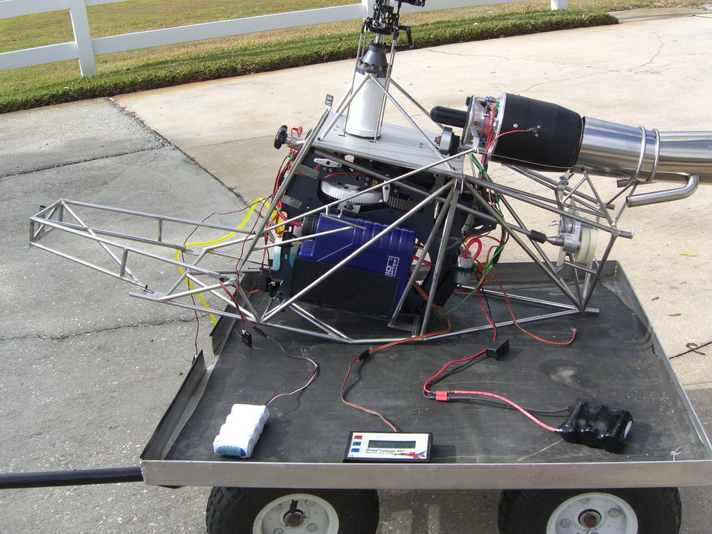
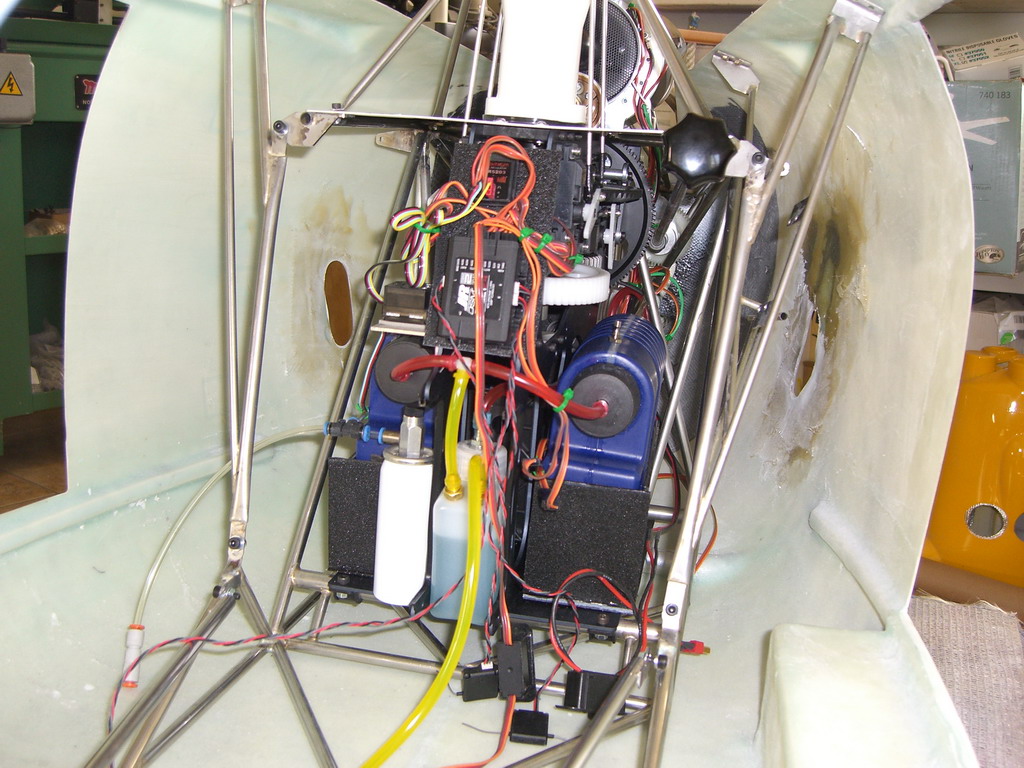
The next job was to finish the mechanics, and I wont bore you with the assembly of them. It was just a progression through the manual until it came to wiring and plumbing. The only change I made to the scheduled assembly was to make some fuel tank holders from ABS as the wood ones weren't in my kit and I couldn't be bothered to wait for them to come from Germany. I also fitted a UAT instead of the Vario header tank and I plumbed the fuel tanks in parallel instead of series. This stops the first one from expanding and contracting dramatically. Then I took the whole assembly outside and ran it up to be sure it fired up. 50% power had the head spinning and the exhaust at a nice cosy 375 degrees. All was nice and smooth.
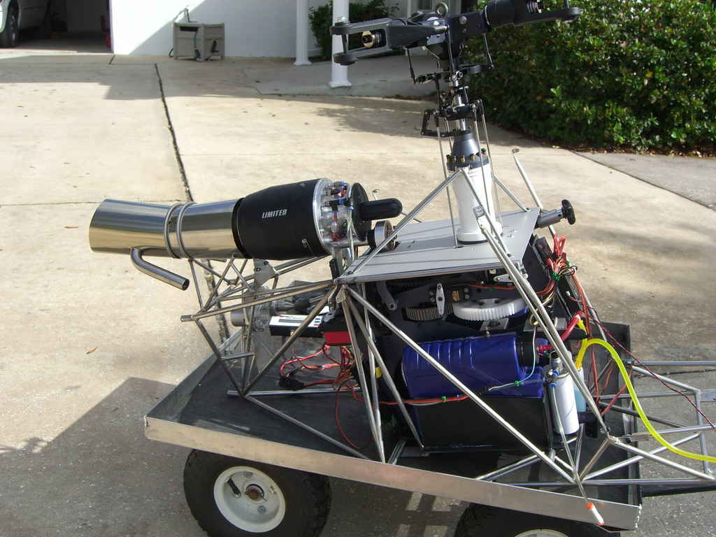
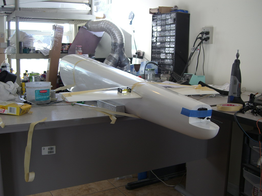
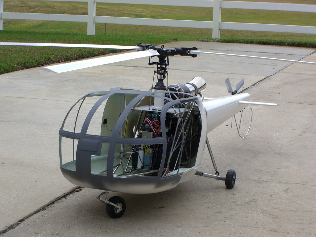
I then managed to get the mechanics into the fuselage. This is not going to be easy once it is painted and I will have to consider carefully what needs to be removed and fitted after the mechanics are fitted.
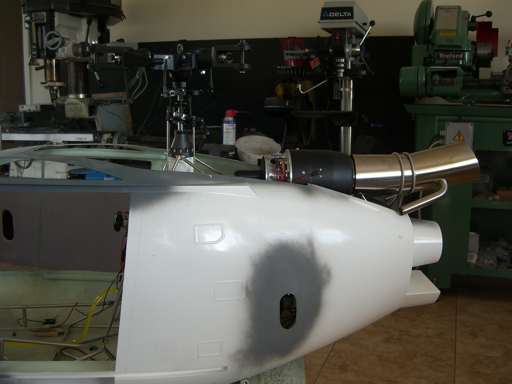
A little trimming is needed around the exhaust vents to get the pipes back inside the fuselage. Also a little work is needed to secure the fuselage to the mechanics at the top as although Vario have made braces from the frames to the tub, they aren't long enough and they need to be bolted through the tub where the bolt heads will be seen. It would be nice if the fixings could be hidden
Tail boom is next, and it's a good job Joe Howard is at the end of the phone. This was one of the more confusing aspects of this build and it's mostly been confusing so far. we decided the instructions were in the wrong order and that although the tail boom was designed to be removable, the coupling of a 6" drives shaft inside when re attaching the tail boom would be very difficult, so I have decided to make the tail boom permanent. Not that it makes much difference in the build as the attachment process still requires the gears etc to pull the tail boom into place and hold it while it sets. However, once its done, I can remove the mechs, install the driveshaft for once and for all and then replace the mechanics.
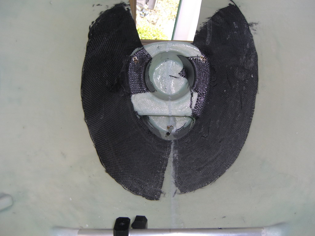
Fixing the tail and drive shaft together required a lot of preparation and the one mammoth gluing session. Inside the tail boom is a tail drive tube with bearings inside 2 formers. These have slots for vertical adjustment and then rings which are glued to the formers and tail tube to fix it in place. Then there is a large fiberglass molding at the front which couples to the main tub. Just to complicate matters, the tail servo is fixed to the tail tube so the pushrod has to be fitted and aligned as well. Anyway after a few hours work it looked like the pictures, and as I had some glue left over I glued the horizontal stabs in as well. There are no lights in the stabs so I don't have to run wires, but there is a light going to go into the tail which will be the turbine status light so I will have to run one extension cable right the way down the tail boom
That concludes 3 days of frustration and hard work. This model seems to have something against me! I wont go into details of what was wrong as it wont do any good, but some of my solutions may be of interest. The main problem lay in the design Vario had come up with to make the tail boom removable. My assumption that they had put the instructions in the wrong order was wrong, but the correct order was going to be very difficult to implement. After struggling to implement this, I concluded that I would never be able to do it with the exhaust in place and so I decided to permanently fix the tail boom in place. However, I would use their system to pull the boom onto the complex mouldings inside the boom and fuselage together
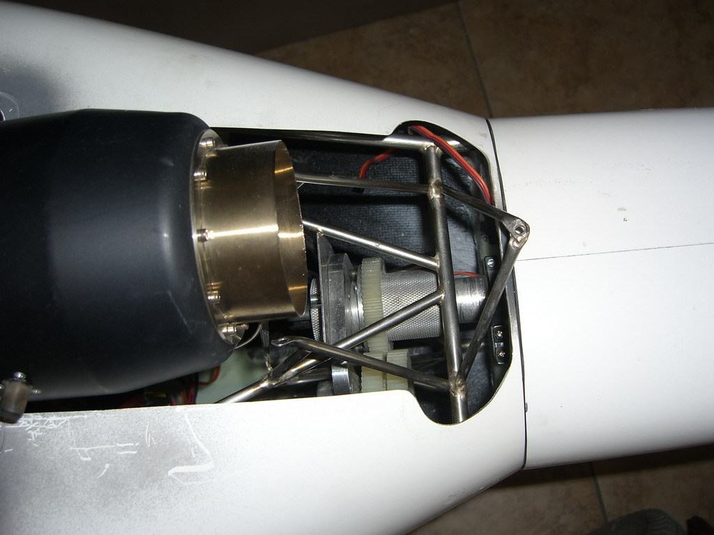
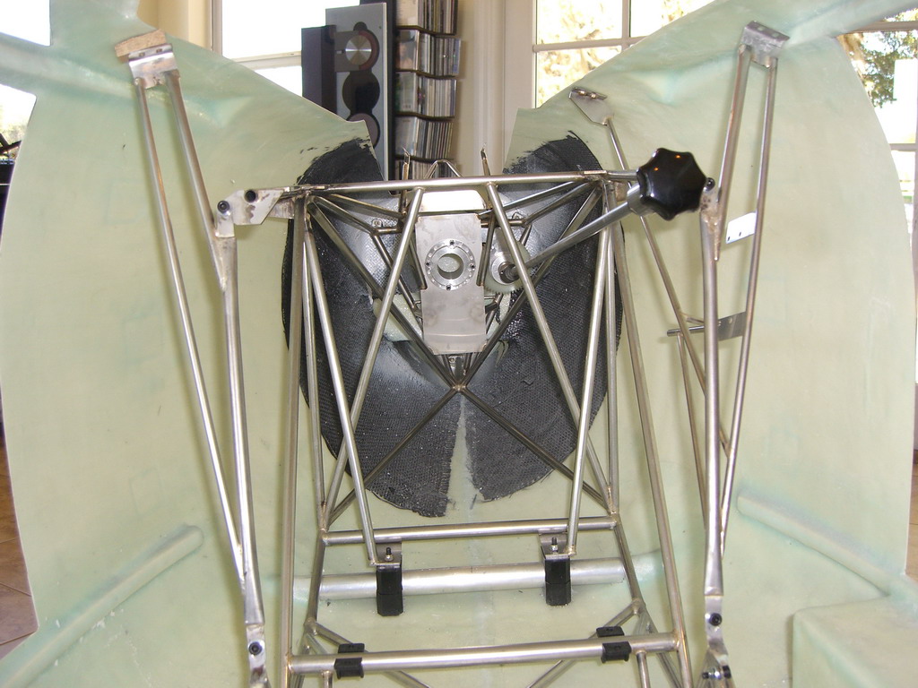
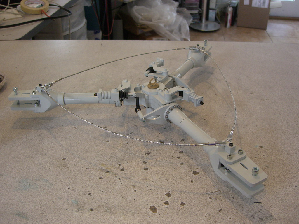
This is the system they designed. It consists on a threaded tube which the tail boom fits through plus an internally threaded tube fitted onto the tail boom. There is a brass ring which you cant see, glued to the tailboom and the tube wont go over it so when you screw the two parts together as they are in the picture, it pulls the tail boom towards the mechanics. The gears go to the handle at the front of the mechanics so you can take the tail boom on and off without having to get your hand in there. If only it was that simple! There is also a tail servo inside there somewhere which had to be fitted and lined up. Well after 2 days of lining everything up and getting it all sorted. I had to fit the tail light and that was a challenge as it all had to be done from inside the tailboom which is 4' long. The way I did it was to get a piece of wire and left the insulation on the end. Then I fed it through the hole in the tail rotor end of the boom and fixed the LED on with some heatshrink sleeving. Then I pulled it back through and cut the sleeving off to leave about an inch. I fixed it in place and now I can spray the tail without having to mask the light. Finally I will be able to cut the heatshrink off flush with the fiberglass. Then I did a final try on fitting the tailboom. The dry run went perfectly.
Now it was time to glue it together so all the surfaces got roughened up and a whole tube of JB weld was mixed up and spread all over the mating surfaces. Once that was done, I fitted the tail boom in place and proceeded to tighten the collar to pull it in. It went in so far and then it stopped. The brass ring had come loose on the tail tube! Now I was stuck. I could take it apart and fix it with 5 minute epoxy but had no guarantee it would hold before the JB weld all over the joint started to set. I decided to fit a tourniquet to the tail boom, got a piece of rope and two old paint stirrers and twisted it up until it pulled the tail into place. Then I cleaned off all the excess JB Weld.
I was very nervous about whether this was going to work or something would break but next morning when I took it off, all was in order
Now I can take the mechanics out, and the scale part of the build can begin, at long last. Well maybe I'll fly it first to see what I want to do about the rotor head. Gonzalo Martinez and Ewald Heim both report nice flying with the head with straight pushrods from the swashplate. I had the same system on my ill fated Mil 2 but that failed and it has put me off. Vario have supplied a system which gives vertical pushrods but the cyclic and collective have to be reversed, which is kind of weird. Also I have heard from a reliable source that it doesn't fly as nicely as the straight pushrod setup. Also I have bought a scale rotor head from Germany which I would like to use, but it is rigid. Very rigid, so I don't know how that will fly. If there is going to be death and destruction I think I would rather it be before I get much further in the this build
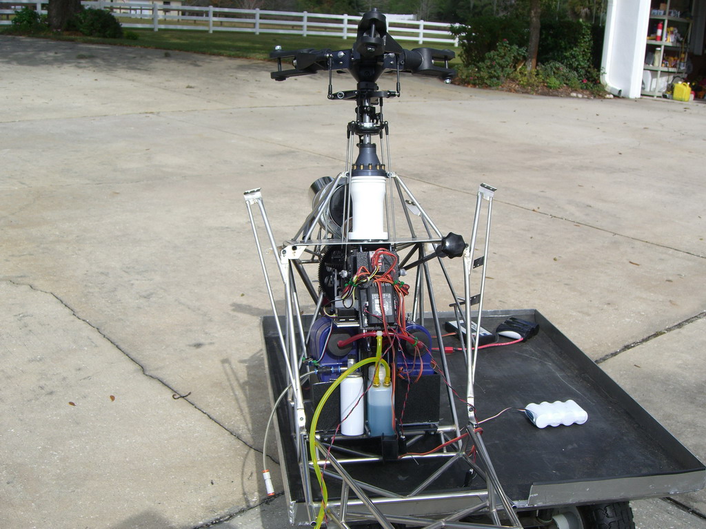
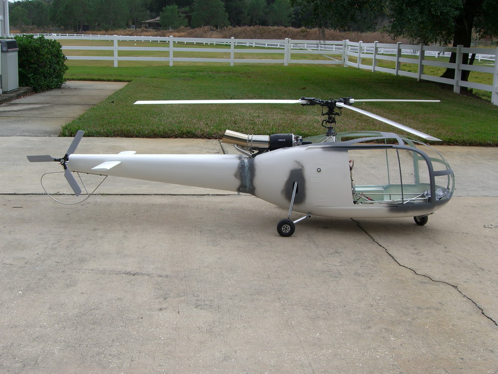
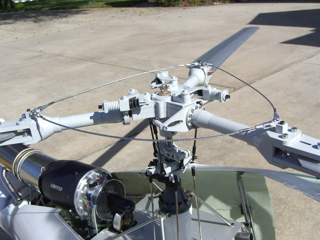
Ok, I decided a test flight would be in order so I fitted the blades and tail blades and hooked everything up.
I will have to tidy up the electronics next time the mechanics come out. I found a GY502 and pulled the GY 401 in favor of the 502. I like to see whats going on so I like a display. I did manage to fnd some more 502's for sale in Hong Kong so I bought those as well and gave someone a deal on my 401's. However, it messed up my wiring even more.
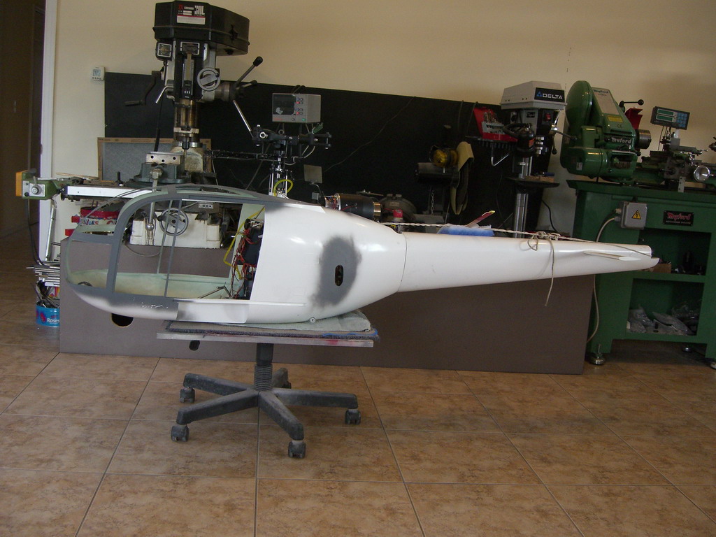
Then I added a little nose weight to balance her up
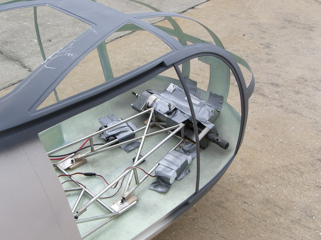
Yes, there's a machine vise in there, 6" of 1 1/2" square aluminum rod and a large solenoid which weighs a couple of pounds on its own. I'm glad this thing has wheels.
The next stage is to try the other rotor head and see how that works. Neither of them will get much of a test but the Vario feels very stable so far but just doesn't look scale. If the other one flies as nice then I'll use that. If it doesn't fly so nice I will sell it to Gonzalo and tell him it's a spare one hehe
Want to see the test flight? It's on You tube.
The scale head was a bit of a surprise. Firstly it wasn't a direct repalcement for the Vario head as it was claimed, it needed metal blades, which are very common in Europe but not here. Fortunately I had some from the Kamov so at least I could give it a try. The second surprise was in the setup. It needed +/- 90 degrees of phasing, which meant that if I reversed the aileron and elevator servos I needed no phasing at all. Then the swash inner was 40mm diameter and the Vario one was 20mm diameter, the thing was very wild when I took off. I reduced the throws from 61% to 30% and added 50% expo. That tamed it down. Then it needed tracking as one blade holder was different from the others, so all in all it took some doing whereas the Vario one went straight on. In the end, they both flew pretty much the same so I have to decide whether I want to incur the wrath of the AMA and keep the metal blades or have a less scale heli and use the Vario blades.
That's a decision which can wait until I see how it flies. Fortunately I can arrange it so that I can switch heads fairly easily and can do a flight comparison of the two. But now, I am easing off for Christmas and will be back on the ball next year.