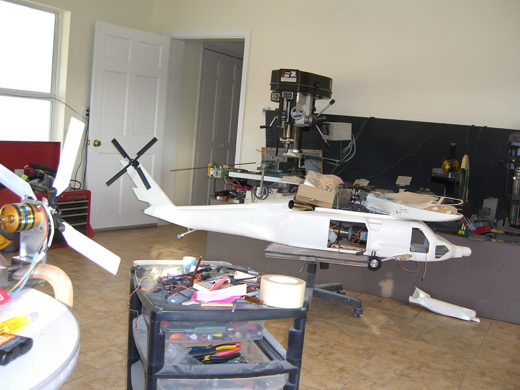
Blackhawk 3
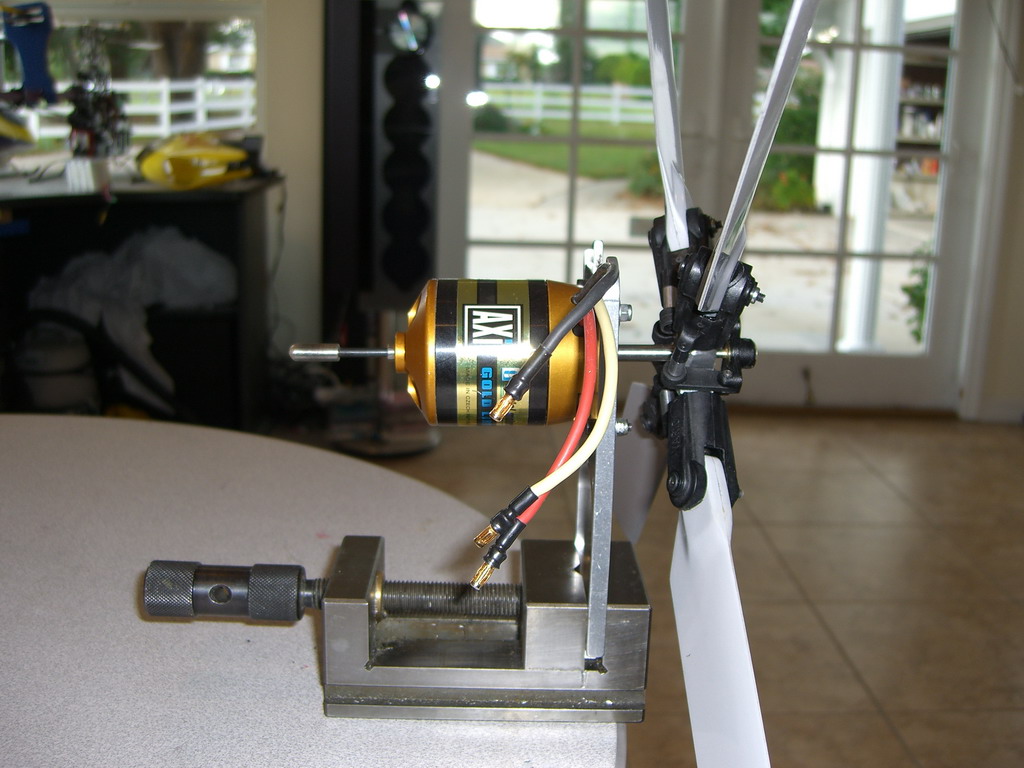
I ran into the problem I was expecting but hoped wouldn't happen. The tail rotor assembly is very heavy. The gearboxes and universal joints makes the inertia and drag of the whole system very high. Too high! The problem is that a turbine doesn't develop a lot of power at low rpms and if it is going too slowly, the computer is telling the fuel pump to add more fuel to accelerate it. If the drag is so high that the turbine cant accelerate it, then the fuel burns inside the turbine with out enough air and the turbine overheats and shuts down. That's what happened to me. The turbine could spool up either the tail or the head, but not both. I really didn't want to go back to a cable drive, apart from the fact I think the cable drive will have problems and a very short life, I just don't like them and don't trust them. I had to find another solution. Then I had an idea. My Grandsons Piccoo z had a motor in the tail, maybe I could do the same. I needed information so I started to put together a test rig.
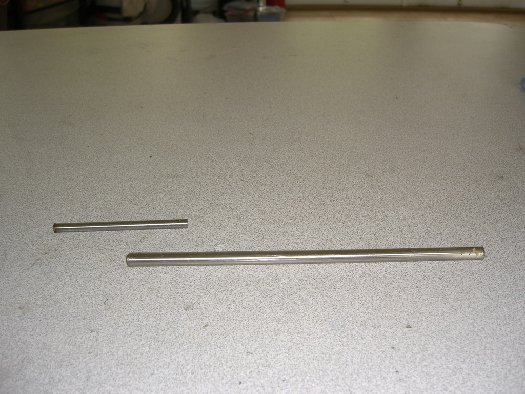
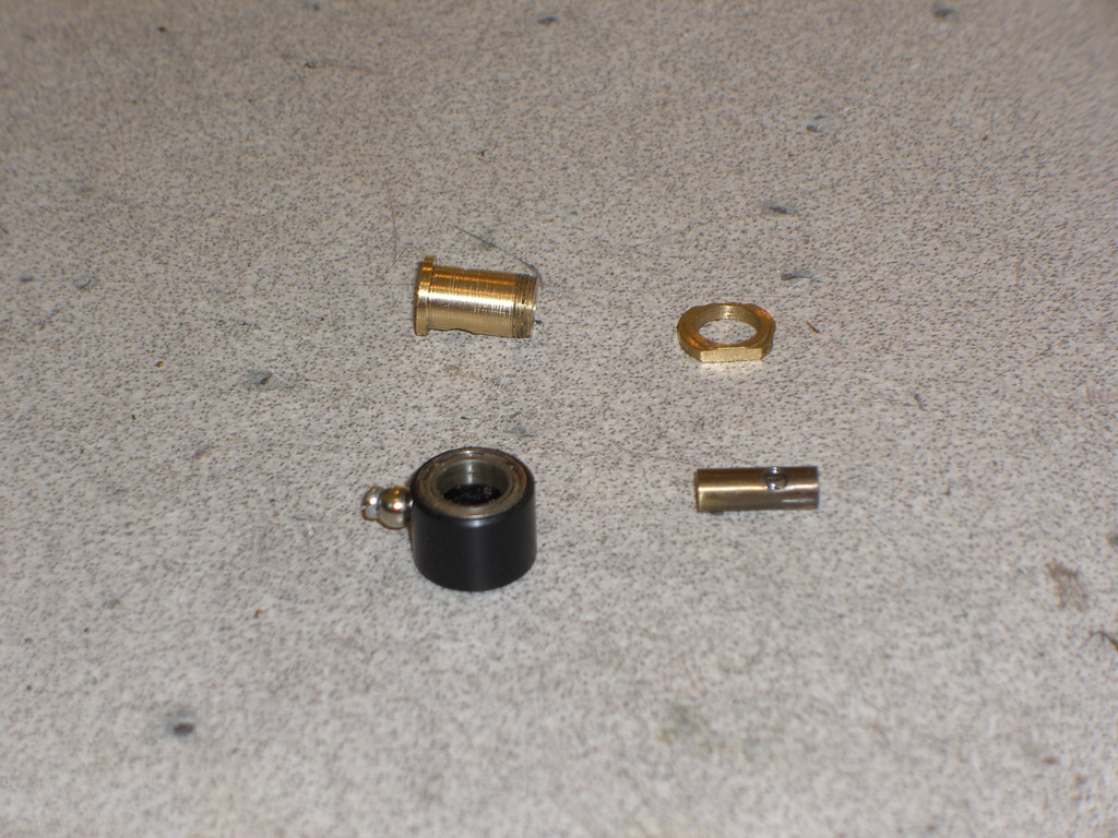
I needed some of these, to make one of these
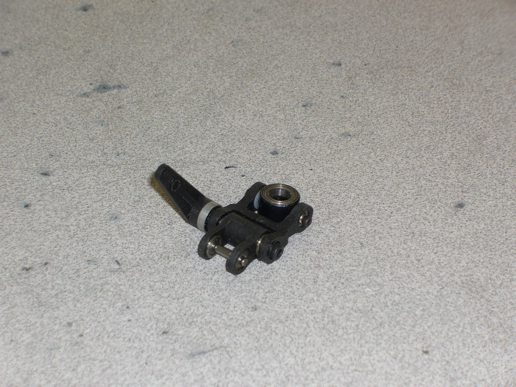
Then I could fit it to one of these
And it should fit nicely into the ball shape in the original tail boom.
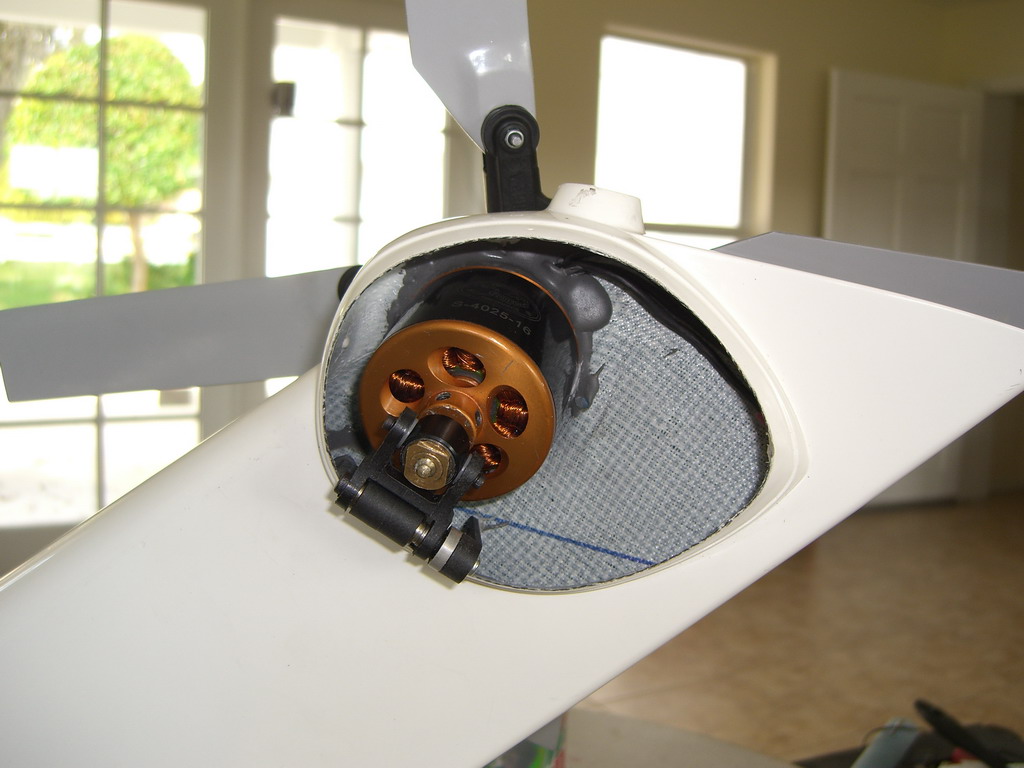
So I grabbed the tail rotor off the Mil and fitted it on, added an elastic band to hold it at maximum pitch and ran it up to 4500 rpm while measuring the power in.
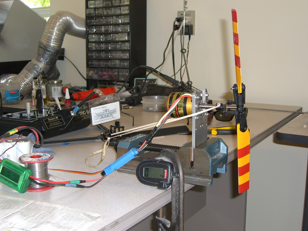
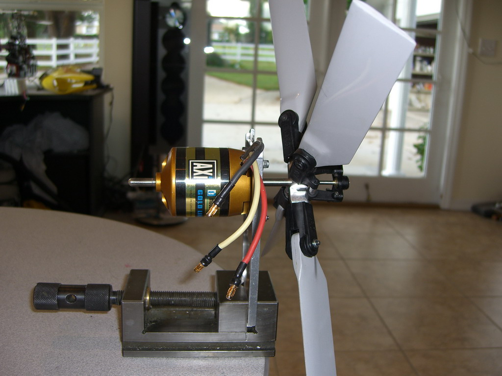
It had no problem running 2 blades at 30 degrees pitch while set at 50% throttle. The battery pack was an 8 cell A123 pack. I need to keep the volts low so as to keep the rpms down so the current was quite high. Anyway, at full speed and full pitch it sucked up 625 watts using 24 amps at about 25v. Although the 4 blade head will have higher drag I don't expect it to need 30 degrees of pitch so I am confident that on average we will be in the 500-800 watt ball park. I will order a Skycrane 4 blade tail setup from Joe Howard and run more tests, but this looks very promising. The model only weighs in at 22 lbs so I can effectively use a 2p 8 cell pack up front and eliminate some useless lead which would otherwise be balancing it. The motor weighs 1 lb so it will need a lot of counter weight up front, but there will be no gearboxes or drive shafts to worry about.
The hub and blades arrived from Joe and this setup works exceptionally well.
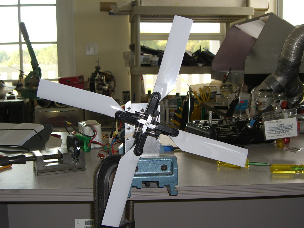
At this pitch setting, about 30 degrees, I am using 50 amps at 24v, and the little vice with the tacho did get blown backwards to that position. It makes a lot of wind.
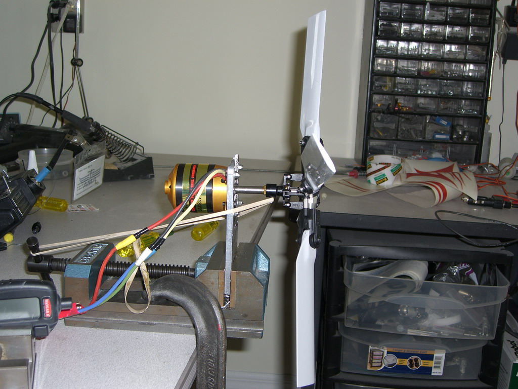
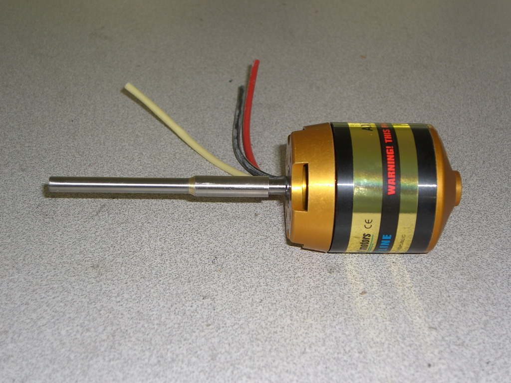
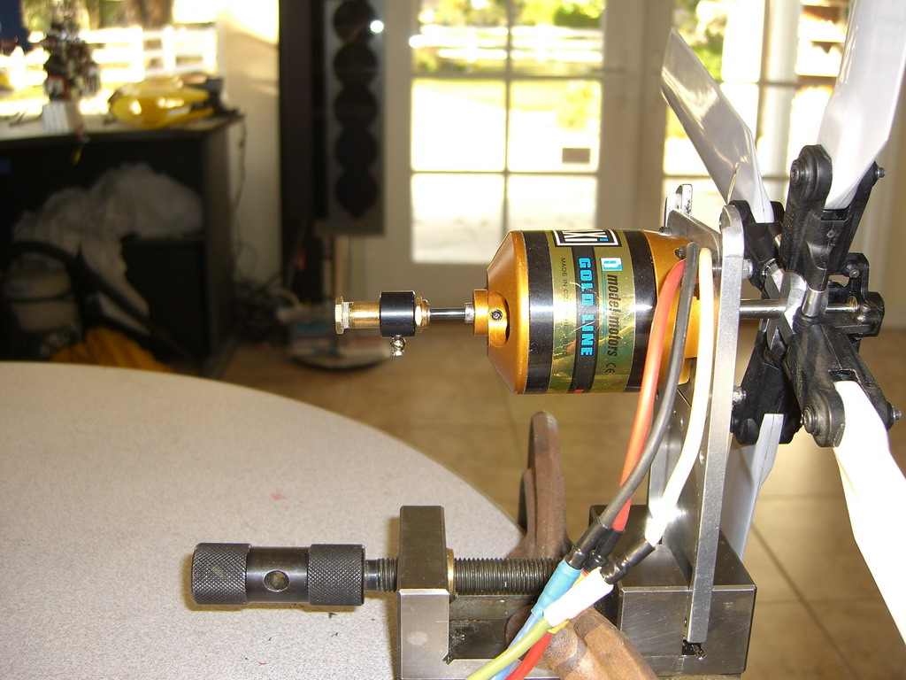
A Hyperion motor should arrive today which is smaller and makes a little more power but at a higher rpm (kV) so I will try that when it gets here. The next problem will be a neat pitch slider and that wont be so easy. It has to get past the motor and still look reasonable on the outside. A quick check showed that any weight in the tail will need 4 x as much in the nose to counterbalance it. A 8s 2 p A123 pack should help a lot in that respect. If the new motor works, it is 25% lighter than the AXI so that will be a help as well.
Well the Hyperion motor was a washout! The motor was very nice but its Kv was too high so when I ran it slowly it sucked up 75 amps and switched the controller off due to overheating. I am back on the AXI now, but with one small change. I decided to remove the shaft and replace it with a longer piece of 6mm steel so I didn't have that joint in the middle. It seemed a potential weak point to me so it had to go. Now it's really smooth, but I do have one minor problem I want to use the turbine controller to set the tail rotor moving. The tail rotor requires a high of -40% and a low of -100% The slider has to go through 0 to get to the upper section of its travel so it goes -100, 0, +100, or in this case -100, 0 , -40. As the ramp up is so slow, you dont notice anything untoward, but I will have to figure some other way to control the tail rotor speed and I don't have any outputs left on my RX. I hope Spektrum comes out with a 12 Ch Rx soon.
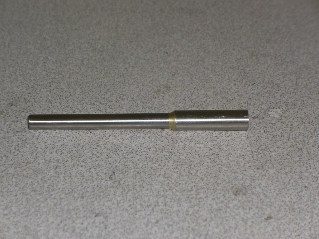
Well, after a long layoff wasting a lot of time waiting for a motor which weighed a lot less but made the power, I gave up on it. This morning I got back to the AXI and started work. I started off by drilling a piece of 6mm stainless rod with a very long 1/8" drill. I cant find a long 3mm drill anywhere in the world and 1/8" are easily available so it got used. Then I cut a 0.8mm groove for the circlip and milled a flat on the end of the tube for the rotor to be fixed to via its 2 set screws. I decided to sacrifice the drill as it was the straightest piece of 1/8" rod I had so I cut the tube to length and then cut a small piece off the end of the part I had cut off. This got brazed onto the drill at the blunt end and then a piece of 8mm brass rod was drilled out to 6mm and CA'd on the rod. Now I could fit the spider onto the rod and I CA'd that on and then drilled a hole through the lot for a roll pin to secure it.
I hope the picture makes a bit of sense of that lot. I measured the travel I needed to gets lots of pitch in either direction and then brazed the rest of the 6mm rod on the other end.
Full travel one way
And full travel the other way. I hope its enough
Next job is to fit the pitch adjuster on to the control rod and figure out a servo linkage. The servo will be very close so I hope it wont be too hard, but thats for tomorrow. A quick test showed that a 5s2p A123 pack at 100% gave exactly 4500 rpm which is right on the nail. A small amount of pitch still in the blades was enough to start blowing pieces of blackhawk all round the workshop. Its sitting about 10 feet away!
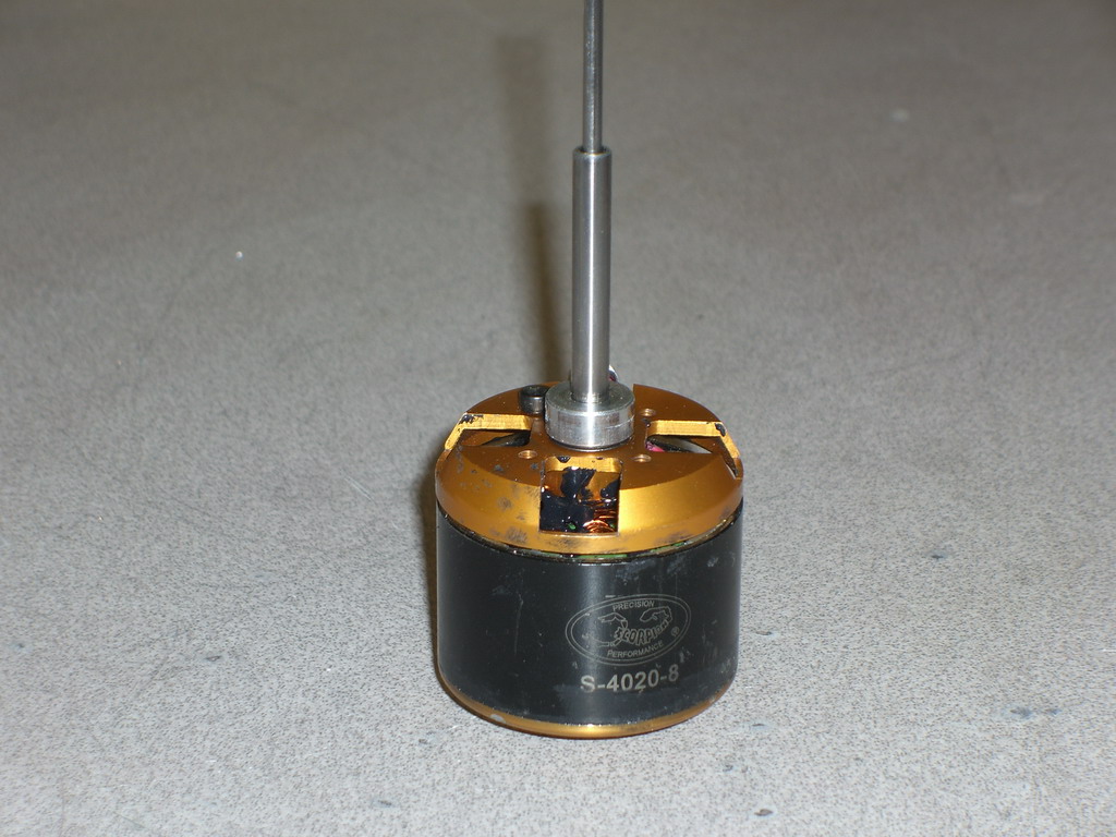
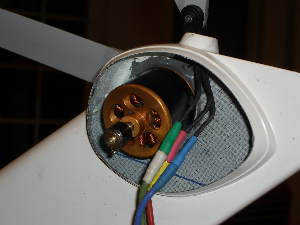
That all sounded very exciting but the crunch came when I did a trial fit in the tail. It was too long! I really needed a shorter motor. I went back to the web and looked and the prototype Scorpion motor which had wasted so much time had now gone into production and one of the winding options was 332KV, in the right ball park. I ordered one and ran it up and at 66% on the governor we were 4500 rpm on the nose. This is the prototype one after a lot of bashing, but it looks the same as the 4025-16 which I was going to use
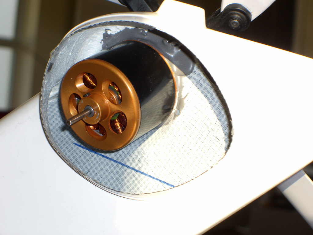
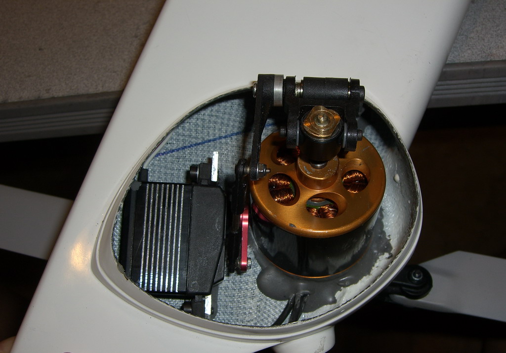
I pulled the rotor off and glued the stator into the tail fin with JB weld, using the shaft as an alignment tool.
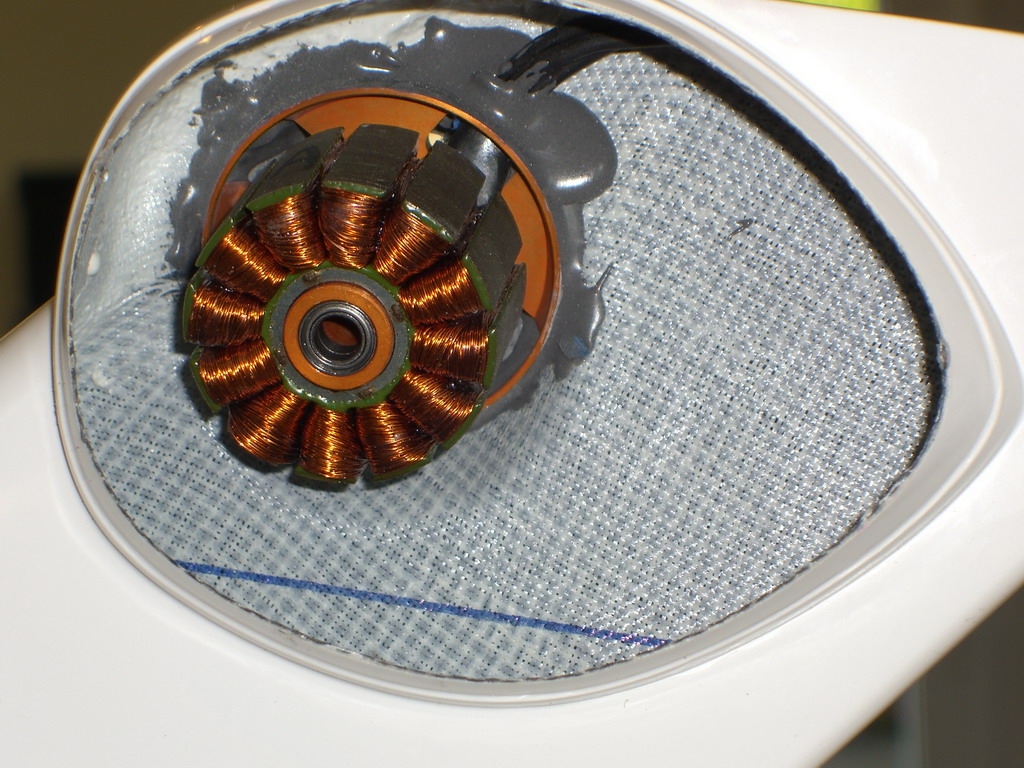
The stock shaft was exactly the right length, but the shafts I had made up were very slightly too thin and this allowed the rotor to rub against the stator. I had to drill the shaft with my last long 1/8" drill.
As you can see, the motor hardly protrudes from the fin, just the pitch change mechanism will fit into the dome on the other side of the fin. The motor now reassembled and I can measure the length of the pitch change rod needed.
Then I had to make up a RH threaded pitch change adjuster. Normally they are left handed so they don't undo in flight, but as this is on the back of the motor, it works the other way. I decided to silver solder a 5mm piece of stainless to the pitch change rod so I had some meat in the brass tube to fit a set screw.
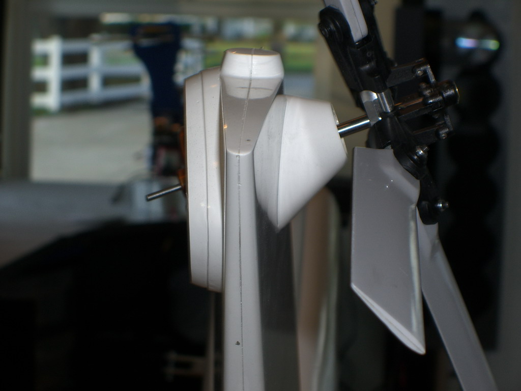
All assembled and ready for a run. It was quite smooth and very strong. I altered the pitch by hand while holding the tail boom with my other hand and couldn't hold it. Even with two hands I had to fight it down onto the top of my Tx so I could shut it down. I has the presence of mind to look at the power and it was using 25 amps at 16 volts at high pitch. Whether it was full pitch or not I don't know, I was too busy trying to keep the blades out of my face. Whatever, I am sure it will be powerful enough, but it will get a lot of testing before fitting to the heli. I need to be sure the JB weld will hold and I think I need a wood brace across the top of tailfin.
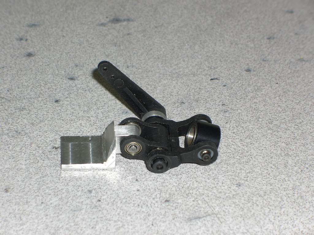
I robbed a Robbe to get this parallel action pitch slider. It had a 5mm mainshaft and so a little work with the dremel was needed to open the gap from 13 to 14mm for the slider.
Then I made up a mount. This is the prototype which wasn't quite right so I made a bigger one.
The beauty of this setup is twofold. Firstly I can set the pitch lever at whatever angle I want, and secondly I can make the assembly compact because of the parallel action section removing the twisting motion on the ball. If its made small the arc is small and the change in angle is large, with the attendant danger of the ball coming out of the arm. Anyway, here it is assembled and JB welded into place. The need for a plywood brace is reducing as the metal and JB weld level increases.
For the past couple of days I have been really sick with some foul disease, so I haven't been able to do much. Machining up this servo mount and JB welding it in place is about as much as I can cope with. This really annoys me as most of America is freezing and its 84 degrees and sunny outside and for Dec 29th, its a record and here I am inside feeling very sorry for myself.
Anyway, its done and all I have to do is to give it a couple of test runs in my B&D workmate and then mount it to the Blackhawk and go fly it. By the time I get to that it will be in the 30's around here and I wont be going outside at all. Watch this space for future updates.