Electric Seasprite
The turbine in the turbine Seasprite had a tail rotor output driveshaft which was quite low in the mechanics. This made the connection to the tail rotor intermediate gearbox and then up to the tail rotor output gearbox fairly simple using a 45°intermediate gearbox. With the electric version I want to use a Goblin mechanics set and keep the tail rotor drive quite high inside the fuselage. This would have made the drive shaft into the tail rotor to gearbox come out not only at a difficult angle but at an impossible place to use. So I started searching around for some 60° gears. I found some and sent a pair off to Darrell Sprayberry as he was interested in using them in the tail rotor drive on the Indy Helis Apache. This has a very steep tail and the original design used a cable drive which was never very successful. Darrell made up a superb aluminum gearbox which only had one problem and that was that it was way too heavy. He then set about machining the gears down by removing all of the excess metal. Bear in mind that at the other end of this is likely to be something like a Vario gearbox with 10 mm diameter gears and the gears we were using were 30 mm diameter so we had plenty of capacity for power transmission in hand. I then started looking at ways of making a lighter gearbox and I found the Vario open 45° gearbox which used plastic gears. This gave me the idea for the basic design and I removed the bearing blocks from this gearbox as they used to bearings to hold an 8 mm diameter shaft. The gears were supplied bored out with an 8 mm hole.
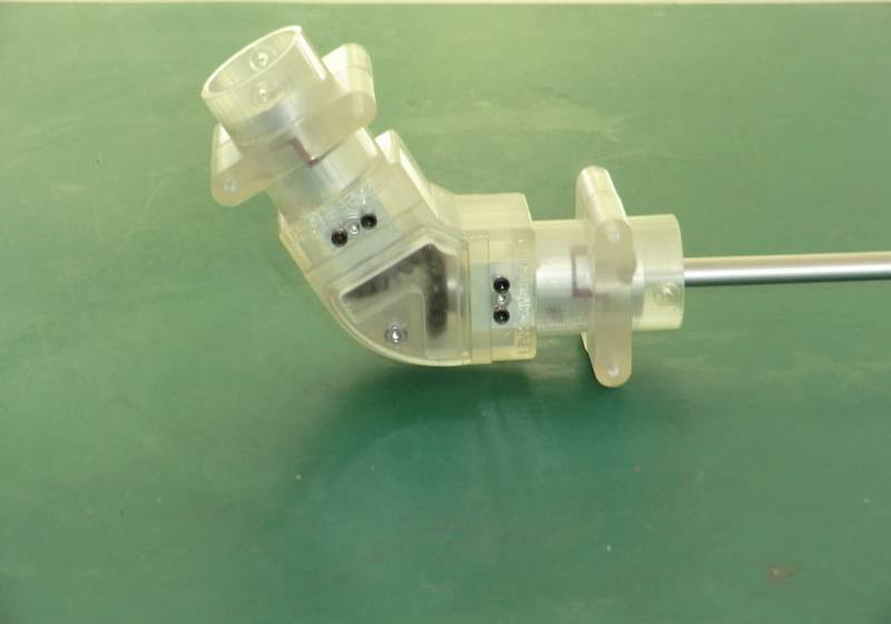
Now it was time to put my 3-D printer to work and although 3-D printer is the common terminology it is actually a rapid prototyping machine and that's exactly what I was going to use it for. I made up several different options on the side frames and in discussions with Darrell we found that after eight different sets of side frames the best ones were actually not only side frames but included the top and bottom as well. This would allow us to keep the grease in and a small panel held in place with one screw and a molded pin would allow easy access to replace grease used in flight and check the state of the gears. The one extremely good thing about using a CAD system and a 3-D printer is that when you ask for 120° you get exactly 120° and so the alignment of these gears came out absolutely perfect. They run very smoothly together. The other option that we took was to mold in a 25 mm inside diameter tube so that we could use the gearbox to clamp onto a tail boom tube and thus perfect the alignment. The whole thing was finished off with 20 mm star couplers with soft inserts which we think will be considerably more durable than the Vario 10 mm versions. This is what the gearbox looks like.
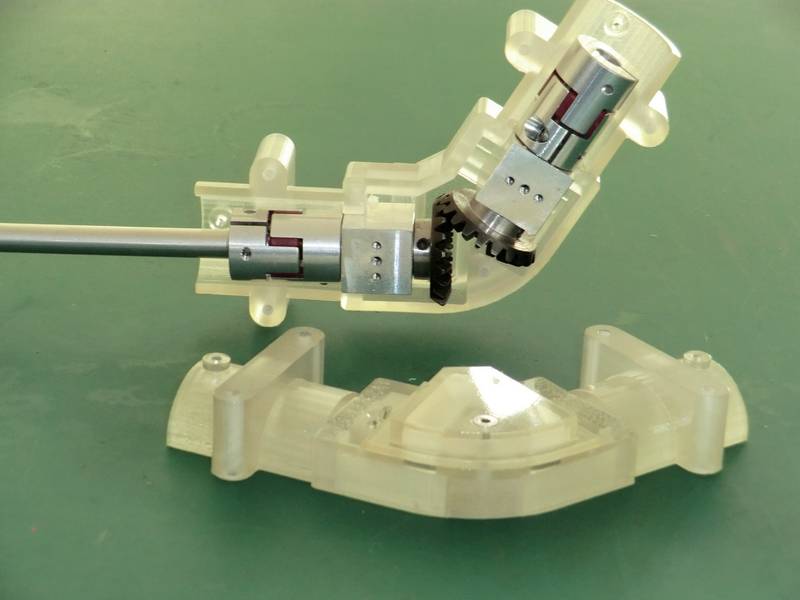
and inside you can see how simple it is
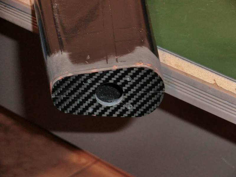
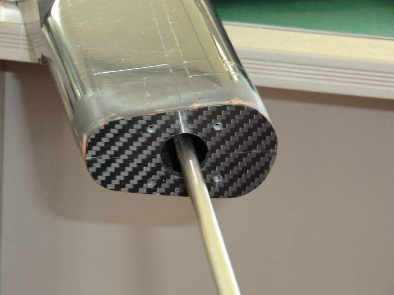
Having built up an over size transmission with lots of bearings in tail tubes, I turned my attention to fixing the tail rotor gearbox on top of the fin. I measured inside and out and found the top of the fin was only 1mm thick, so I decided to make an aluminum plate to go under the top of the fin to bolt the gearbox to. After creating a precision masterpiece on the mill and boring an 18mm hole in it to take the gearbox output shaft in perfect alignment, I discovered that the inside of the fin was a mess where the two halves had been joined together and there was a large blob of cured CF right over one of the mounting holes. There was no way I could reach that to smooth it out, so it was back to the drawing board. I found a scrap of 3mm CF plate and cut it pretty close to size and glued it in place on top of the fin, but after I had bored an 18mm hole and found a piece of 18mm metal I could use to align the two holes. Taped down, left overnight and then sanded and filled and this is what I ended up with.
Then I drilled and tapped the 3mm holes for the gearbox and immediately ran into my next problem. 20mm couplers dont go through 18mm holes. I cant fit the coupler on when the gearbox is in place, so I had to open my hole up to 20mm. Now it fits.

Now I can use the shaft in the gearbox coupler to position the intermediate gearbox
You would never have thought that simply inserting a prebuilt driveshaft would have been so difficult. Of course the driveshaft up to the tail rotor gearbox would not go around the corner so I could not inserted assembled. Once I had it lined up I could not get the tube out through the hole. And so it went on and on. I ended up making a plastic right angle mount with a slot to take a pan head screw on one side and a normal Head on the other. Then I drilled some holes to mount this to the gearbox. When I looked at the finished job, although fully functional it was not very pretty and I thought it would be nicer to remold both parts as one. It turns out that there is a discrepancy between two faces of .007° and solid Works would not allow me to mate those surfaces. When I checked I found that there would have been a microscopic gap where the two were joined and any stress would have broken the amount away from the gearbox. So rather than try and find out where my discrepancy was,I linked two different surfaces which now pushed the errant surface into the gearbox rather than away from it and of course when he was printed it came out as one nice strong solid joint, albeit with a deviation of 0.007 degrees .
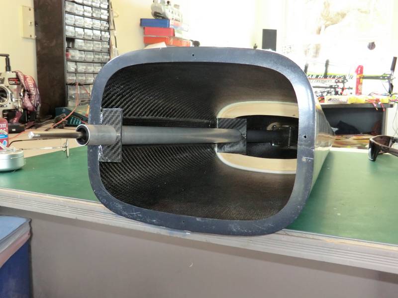
I then cut two pieces of carbon fiber sheet to support the gearbox mount, glued them together, and then drilled holes to mount the cap head screw that you can see, and a pan head screw you cannot see on the other side of the tube. This fits into a slot in the gearbox mount and with a little bit of jiggling with my allen wrench, it is tight. It was vitally important that the driveshaft into the tail rotor gearbox came out centrally from the mounting hole as its fitment into the gearbox is rigid.
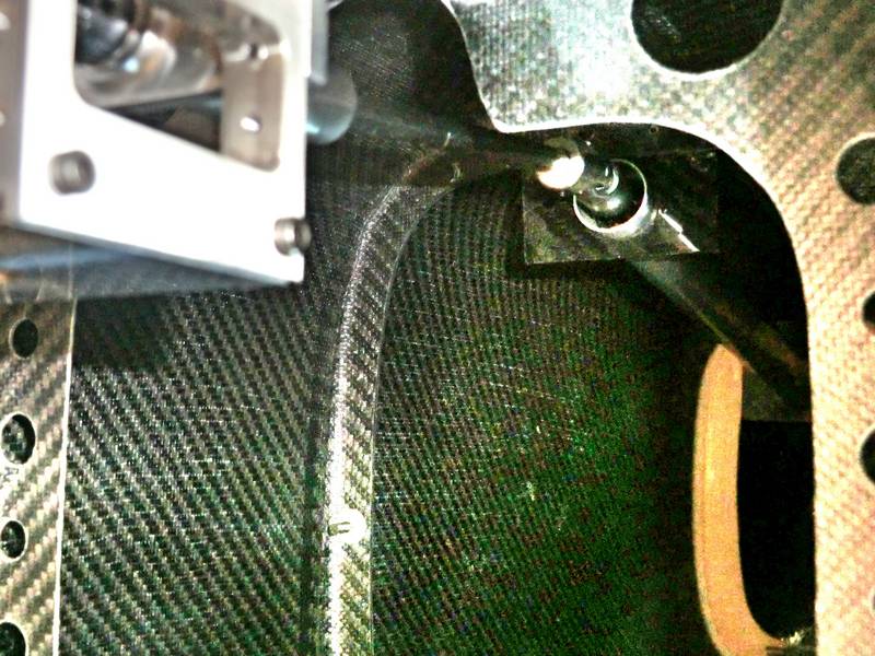
The driveshaft from the mechanics had to ride as high as possible, so that defined the position of the intermediate gear box. A large quantity of epoxy made certain that the two pieces of carbon fiber would not move. Then I cut two more pieces of carbon and drilled 1 inch holes in them to slide them over the 25 mm tail boom tube and glued them to the formers inside to ensure that the tube does not move. Once they had set a small blob of PFM locks them in place but allows a small amount of movement to absorb any vibrations.
After many different attempts to get the tail rotor gearbox to align perfectly to the shaft I ended up giving up! The problem centered around the fact that I had to take a piece of steel, machine one side of it down to fit accurately inside the Vario 8mm driveshaft tube, and then machine the other end exactly to fit inside the input of the tail rotor gearbox. My lathe is not precise enough to allow the piece of metal to be taken out of the Chuck and turn around and still remain absolutely central. So I asked Darrell to machine a piece up for me on his lathe which has a collet Chuck. When the parts arrived I had to machine them to size and they kept breaking my carbide tool bits for some reason. When I got everything exactly to size the last job was to cross drill the 6 mm diameter part with a 2 mm hole for the pin. Nothing I had would even Mark this material! When I asked Darrell what it was he said he didn't know, it was something that had been taken out of electric motors and it was quite hard. That was the understatement of the year. I know that if I tried to drill it with a carbide drill the drill would break in the hole.
In order to make some progress with this model I decided to fit a Vario dog bone coupler which has the plastic socket and the metal dog bone. I had everything set up as far as the gearbox was concerned and I just had to cut a piece of 6 mm tubing, machine a piece of steel to go inside the end, and cross drill it with a 2 mm hole for the pin. As everything is perfectly lined up I am less concerned about the durability of the coupler than I would otherwise be. I will run it as it is and keep an eye on things, but meanwhile, Darrell has suggested purchasing another star coupler with 6 mm holes and using one side to take the drive out all of the 8mm shaft and the other side to drive the 6 mm shaft into the gearbox. I will order the parts but right now I need to get on and get something else done as this is driving me nuts.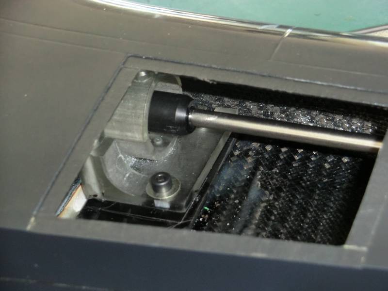
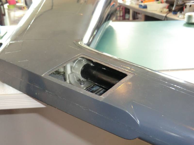
As you can see from the picture the intermediate gear box mount has been moved as far towards the front of the fin as possible. This leaves me lots of room for a servo to be mounted in the back to get a nice direct pushrod to the tail rotor pitch control.
The 20 mm coupler with the 6 mm diameter hole in the middle arrived so I fitted one with an 8mm hole to the shaft coming out of the gearbox and made up a new 6 mm shaft a Vario driveshaft. I cut this length and slid it into the tail rotor gearbox input and fixed everything in place. It wobbled! The problem is that as you spin driveshaft going into the tail boom, you can see the tail rotor go round and when it stops it goes back about a quarter of a turn. It also feels odd. So, I took the shaft out and looked at it and when I put it in my lathe, it was obviously bent. I put it on my granite worktop and it was like a pretzel, and I definitely could not straight it out. This was a brand-new driveshaft. I checked the one that I had with the plastic coupler on it and that was dead straight but too short. I got the rest of the driveshaft and check that and that was all bent as well. I found some 6 mm tubing with a 1 mm thick wall which was precision drawn, and I cut a piece of this and made a new shaft. This was straight! It also had the advantage of not needing plugs putting in the end's to strengthen it where the couplers were going to be mounted. The disadvantage, of course, was the increase in weight but that was marginal compared to everything else going in the tail.
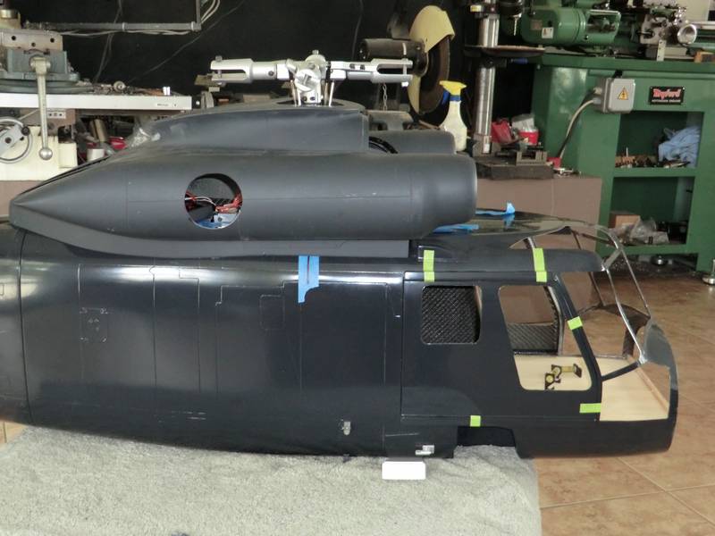
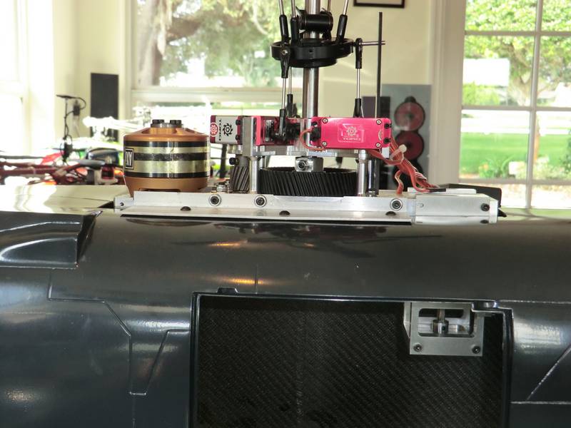
The next job was to cut a hole in the top of the fuselage to take the mechanics. After I had cut it the edges had lost all of their rigidity and needed bracing so I cut two pieces of quarter-inch thick plywood 1 inch wide and include them in place along the sides of the hole, and then cut for small C sections to brace round the curve of the fuselage. Then I cut a very large D shaped piece of wood from 3/16 ply to mount across the back. The front was still very rigid due to the shape of the molding. Once the epoxy had set I've mounted the mechanics place carefully lining up the main shaft to a mark on some tape on the side of the fuselage and centering them exactly. I drilled 6 4 mm holes, and bolted the mechanics in place. It immediately became obvious that I had a bit of sanding to do to allow the driveshaft clearance of a wide carbon fiber former molded into the fuselage.
Now it was time to mount the tail boom to the fuselage tub. Some very small guide holes had been drilled so I opened them up to take 4 mm bolts and include 4 mm bolts inside the tail boom with epoxy. This allowed me to easily mount the tail boom to the tub and remove it again if I needed to. Eventually it will be epoxied in place. I made up A driveshaft to go from the tail to the mechanics and fitted universal joints on each end. When I fitted it in place the angle was quite steep so the tail boom came off, the tail tube came out and was shortened as was the driveshaft. I made up a new intermediate shaft and now the angles are very small. Unfortunately they do not photograph very well but I have retouched them as best I can.
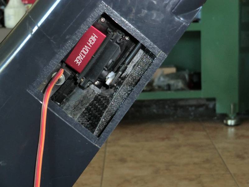
The tail servo was screwed to a piece of CF and glued into place. It may look twisted but the pushrod follows the back of the fin and that is at right angles to the top plate where the tail rotor gearbox is mounted.
Now for a temporary wiring job and to progressively run in the gear boxes and transmission to see if this thing will keep going or fall apart.