Electric Seasprite part 2
The initial run was on a 6S battery and it made some funny noises. At 1/4 throttle with the head doing about 10 rpm it sounded like a big radial engine at idle. I looked inside and I could see the tensioner rattling away as the universal joints rotated in the transmission. The vibrations of the tensioner got worse as I speeded up, so I took it out. That solved that problem, but whether I need a tensioner or not remains to be seen. Then I fitted a 12 s battery and ran it up to 1400 rpm. It sounded quite sweet and all you could hear was the gear noise. No vibrations and no explosions.
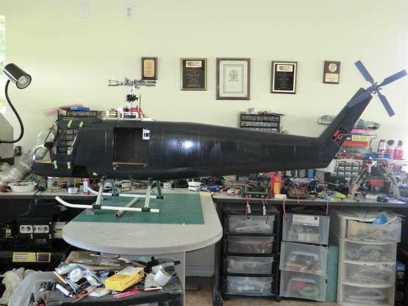
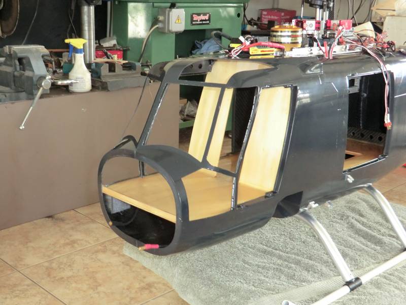
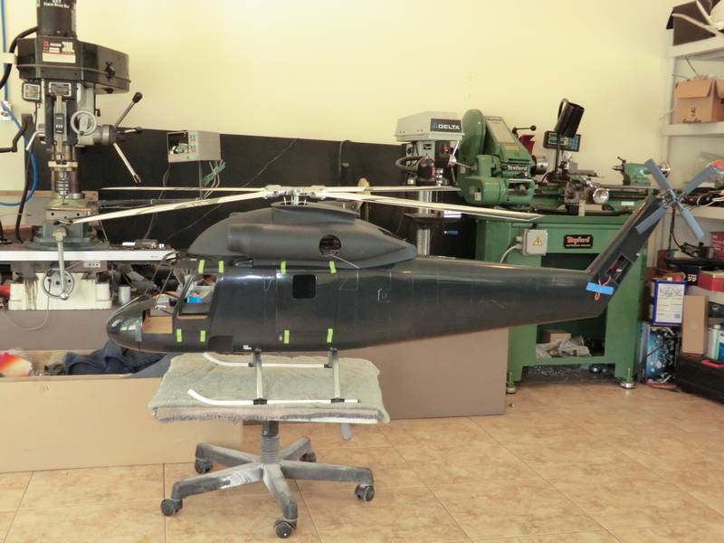
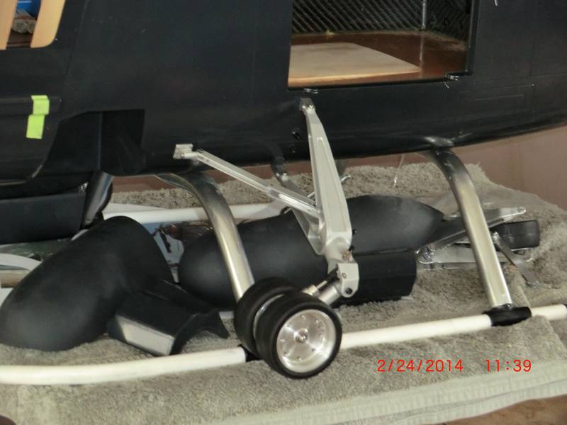
The next step was to glue the tail boom on and I ran a wire for the tail servo and some lights on the fin while it was apart. I bolted it up tight and removed the excess epoxy with some acetone. Then came the landing gear! I dug around i my junk box and found some cross struts from a coax and some skids from a 47G and glued them together. Then I glued the assembly to the bottom of the fuselage with PFM. This will allow me to remove it later and fit the hydraulic landing gear, but first i have some flight testing to do so I need to get that done before getting into detailed work. I would hate to have a tail failure and try and land a spinning heli on that beautiful landing gear, so the temporary skids will do until I am confident in the mechanics.
It also makes correcting the CG a lot easier with skids than wheels and with the addition of only two small pieces of lead everything balanced out when 2 6s 8000mAH batteries were fitted in the nose
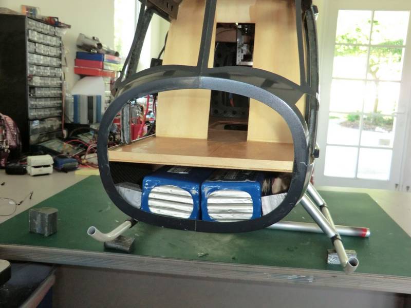
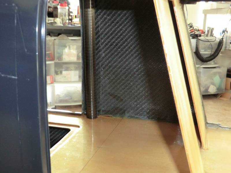
I will fit the two 2s LIFE battery packs inside the fuselage behind the lead as they dont need to come out for charging. I fitted a CF tube inside to carry the Rx power cables.
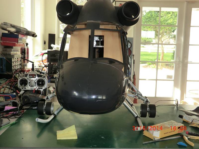
I was running out of reasons for not trying to fly this model so I bit the bullet and fitted the 770mm blades and took it outside. I expected the blades to be too short but they dont actually look too bad. Maybe I will get some longer ones later. Other than needing a bump in pitch to get the model to hover at mid stick, there was no major surprises. One or two minor niggles but I hope to be able to solve those fairly easily.
This is a video of the first hover. The odd noise seems to die away as the flight progresses, but I will have to check things over carefully to see if anything is coming apart.First hover
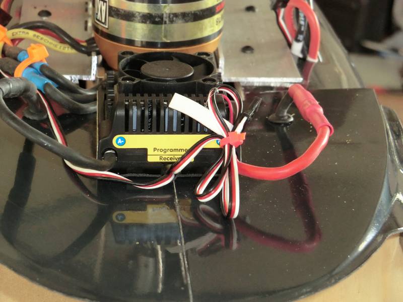
The motor dipped down in power twice during the flight and I wonder if it is due to where I put the ESC throttle cable. If it is, it is surprising it didn't do it again.
The motor power cables were a problem until my wife suggested running them up the door frame and into the cabin roof. This cut the run down from 3' to 14"
You can just see the white wiring on the black cable on the door frame.
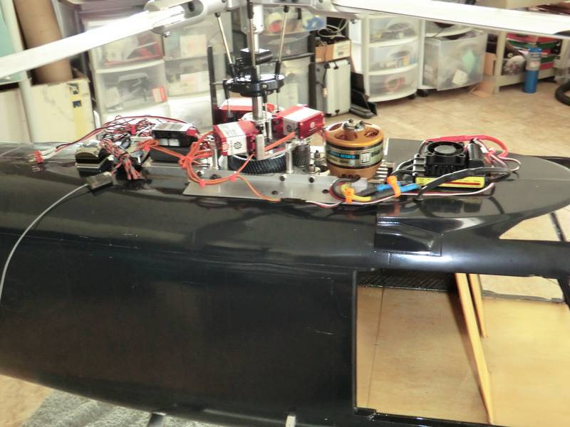
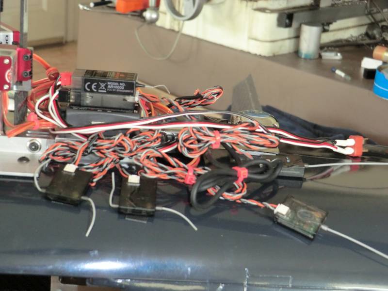
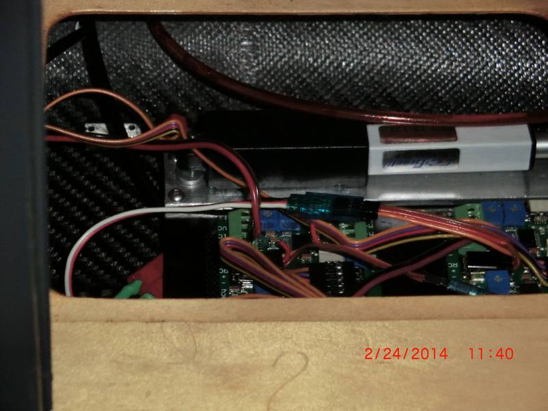
I wanted to continue to use the V-bar as a stand alone unit with its own receivers and add another receiver for the tail gyro. I like 611's dumbed down to 502's drivinga powerful servo. However, it did leave a bit of a mess at the back with all these receivers.
I rewired everything so the receiver was driving the V-bar and reconfigured the v-bar. Another test flight showed that I was getting a couple of "misfires" from the motor at the beginning of the flight. Just 2 and then it was fine, bit when the heli drops like a rock and then leaps back to where it was it does make your heart stop for a second. That turned out to be the ESC and I fitted a power Jazz from the junk box which is way overkill for this heli but it worked. Once I had confidence in the transmission, I ventured into forward flight. Its a difficult video to watch as it was a crappy day but it was flat calm and made for easy flying.
I had fixed the top and front dome on with magnets thinking I would take them off ach flight to connect and disconnect the batteries, but after I had done it, I realized that this was bound to cause premature scratching of the paint in this area as the covers had to be slid off, over the fuselage, so I decided t reroute the receiver battery cables to the front so I could plug them and the power leads in with the front clamshell doors open.
Then I discovered another problem. I thought the final link in the transmission would be easy and used some universal joints from SDP-SI. I had heard others were using these things with success so I bought some for about $20 each and fitted them. Now, when I turn the main rotor slowly, a clunk can be heard and there is significant play in the universal joint. So, I have ordered some with needle roller bearings and a speed rating at 5500 rpm. The SDP-SI ones were plain bearing, not even hardened and rated to 1750 rpm. Lesson learned there. There is more to this story and I'll explain it all when I get the universals and show you the fitting of them. So for now, all the doors and the clamshell are taped in place and the top is on and I await the arrival of custom universal joints. This is how it looks so far.
After a bout of flu which laid me out for two weeks, I finally got to pressuring the suppliers for these universal joints and managed to get some in just before Christmas. While I was changing that part, I decided I would make a change to my drop-down mechanics and fit a larger pulley so that the tail rotor speed was reduced from 5600 to 4200. I thought that would be a simple thing to do but my brain was not functioning and when I tried to reassemble it I realized the belt was going to be too small. So I ordered a whole selection of different size belt's so I could play with different pulleys and tail speeds. So the first job was to reassemble the drop-down system and the easiest way to do this was to take the mechanics out of the fuselage.
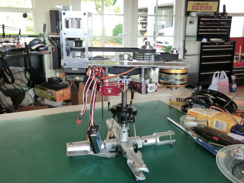
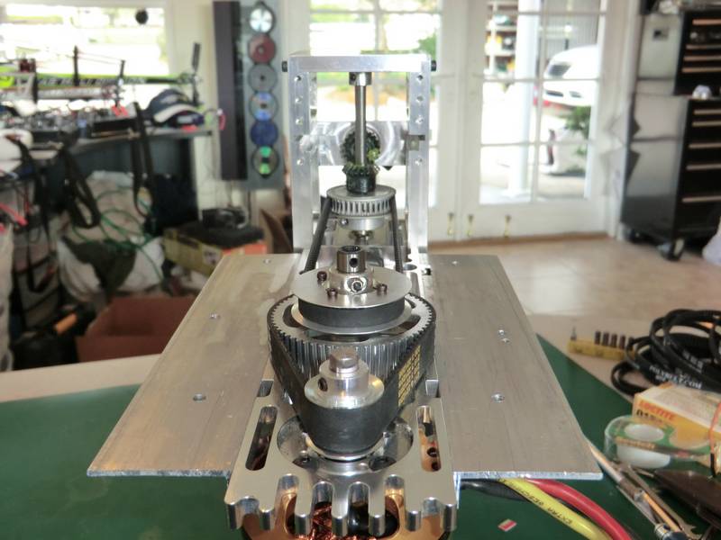
Having a complete selection of belts meant that I could dispense with the tensioner and get one that is exactly the right size. the next job was to align the two gears to get a smooth drive and I added some of Vario's new sticky grease which they claim will not fly off the gears. You can see a close-up of the universal joint.
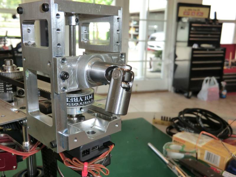
While I was looking through the spec sheets on these universal joints I noticed two points that the manufacturers wanted me to take note of. Firstly the two shafts should be as near parallel as possible. This will reduce the windup which will occur as the shafts rotate. This is something which I could not change but I got them as close as I could. The second thing was that the yokes in the center of the universal joints have to be parallel. This meant drilling the setscrew in the universal joints in exactly the same location and putting a flat on the stub shaft at each end which were both horizontal.
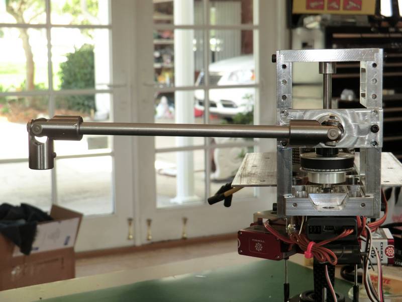
This meant taking a little extra time to set up the milling machine and trying to figure out the best way of holding these universal joints so that they were always in exactly the same position but the results were worth it. Running the head up to speed with no blades on showed that the drive train was much smoother, but now I have to wait for Christmas to come and go before I can get out and do some test flying. I want to get at least six flights on this thing and check for any play in the drivetrain before I progress to completing the model. There is nothing worse than seeing several months work spiraling in because something has gone wrong in the tail Drive.
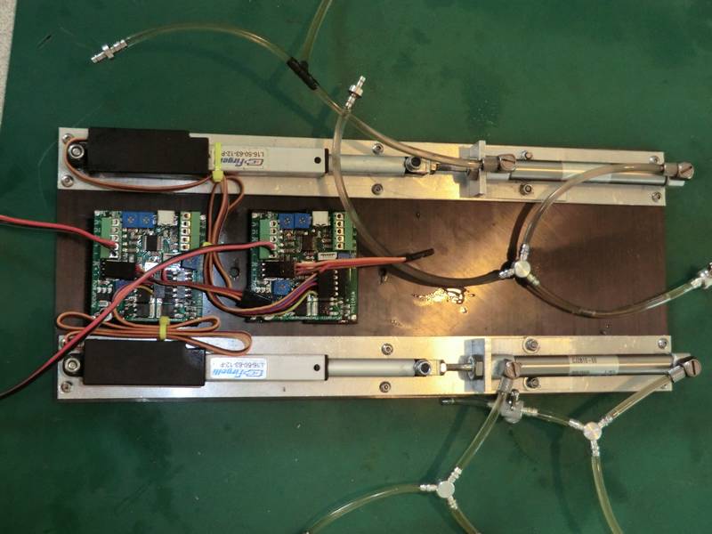
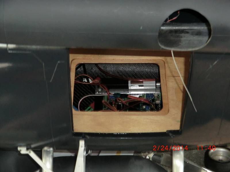
After several hovers and gentle flights, the results were very encouraging. The transmission is very smooth and much quieter with no resonance. So it is time to progress to the next step and do the landing gear. The first job was to make up a small panel with the hydraulic system and electronic driver boards.
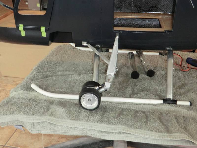
Then I fitted the landing gear, which fortunately just cleared the temporary skids I had glued on the fuselage, so I could test their operation.
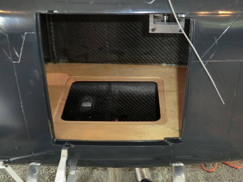
Next, I have to install the panel under the floor and hook everything up, but I will make sure everything works before I drill holes to pass the hydraulic lines through
After a long break while I sorted out a few medical problems, I got back onto sorting out the landing gear. It proved to be a nightmare and took over two weeks of messing around with lots of oil and pieces of pipe. Finally I found the correct way to solve the problem of no bleed nipples and get as much oil into the system as possible. It is not possible to fill the entire system with oil as the cylinders are air cylinders and have a buffer zone at the end of the travels. This buffer zone is to prevent the piston slamming up against the end of the cylinder and is simply a small amount of air trapped after the nipple and gets squished as the piston passes the nipple. Consequently there is always air in the system and it seems to leak out and get into the pipes. Fortunately the amount of air is small and can be compressed enough to force the landing gear into position and once it has forced it there, when the actuator releases, the piston moves back and takes the pressure off the landing gear cylinder.
I have drilled holes for the connectors which will couple the landing gear hydraulics to the landing gear. The control system is now underneath the floor inside the fuse, but not hooked up yet. I can't think of a good reason to go through all of that aggravation again, only to have to take it all apart again to paint the landing gear and the fuselage.
The next job I did not want to do was to hinge the front clamshell doors. Getting the hinges in the right place and of the right type was not going to be easy and I knew I wold have to make the top one. I could not start the top on until the middle one was done so I fitted somre small brass hinges. Even the tiny weight of the CF door was enough to start distorting them and splitting them apart. So, I had the idea of soldering the outside ends of the hinge in plaqqce so they could not distort. Then I bought some 25 thou brass sheet and started cutting filing and sanding and ended up with these.
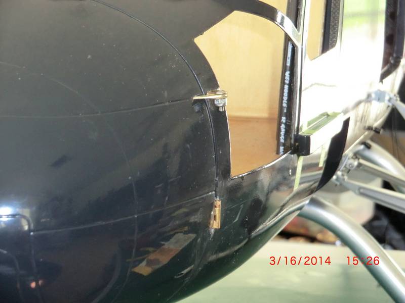
A major part of the difficulty was that the flange I was mounting the hinge on was only 1mm thick CF and by the time i had cut a recess in it, there wasn't much l;eft to work with so i mixed up some micro balloons and epoxy and make a backing from them to be mounted to. The top one could not be mounted until the bottom was fixed and vertical and the the hinge point could be defined for the top.

And then to keep the doors closed, a pair of magnets glued in place. Thats 5 days to wait for the glue to dry in each part of the assembly

Now the doors close with a satisfying clunk and need a knife blade to open them, but there will be lots of things to grab hold of when its finished. The nut and bolt in the top will be replaced by a steel pin glued in place but I may need to take the doors off to paint them so the nut and bolt is temporary