Electric Seasprite part 4
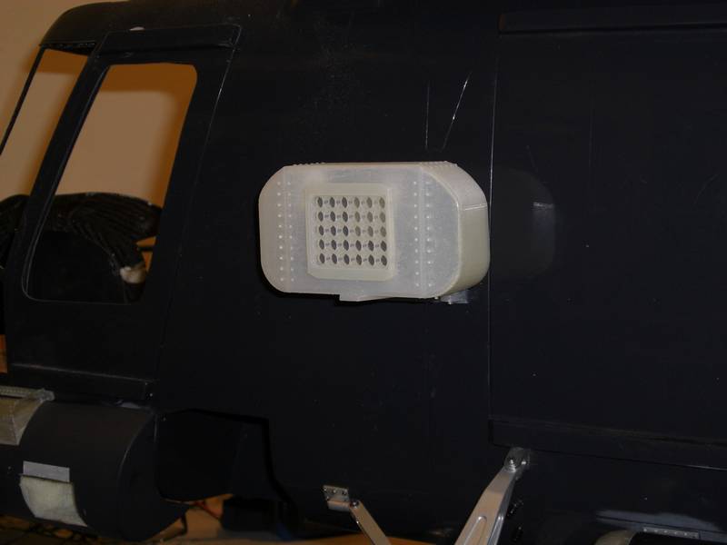
The last few days have been spent on making the flare launcher for the side. It may seem simple but gave me some grief in keeping it light and as it is made up of several parts of differing colors, I had to build it out of different parts as well and they all had to fit together perfectly. I confess it didn't happen first time, but the recalcitrant part, the bezel which goes around the holes, only took 30 minutes to print. This is the result
Rather than make deep tubes, I am going to paint the inside of the box black and the inside of the tubes black so it will appear they go to the back.
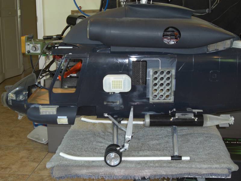
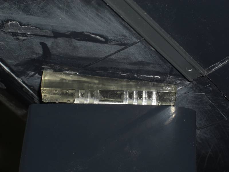
I changed my mind about that and made deep tubes. They still dont go all the way to the back, but when painted black inside and a piece of black CF behind them, you wont be able to tell. The next and last big job is the sonobuoy ejector tubes. I made a bezel and tube holder separately as the bezel needs to be painted red and white stripes, and the tube holder is not a tight fit in there. It is hinged at the bottom so it can be leant into the helicopter to be reloaded so there is a gap all around.
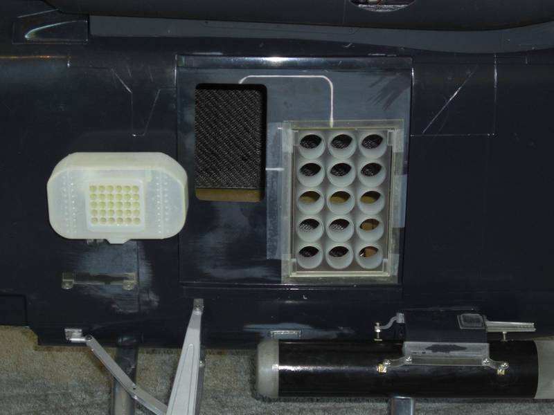
This will also have a piece of CF on the back, but as it will be visible from inside the cabin and I may put the operators station in there as well, I might mold tube covers to fit into each tube. While I had the dremel out, I cut out the hole for the window and filled in the mold marks for the window which is on the G model.
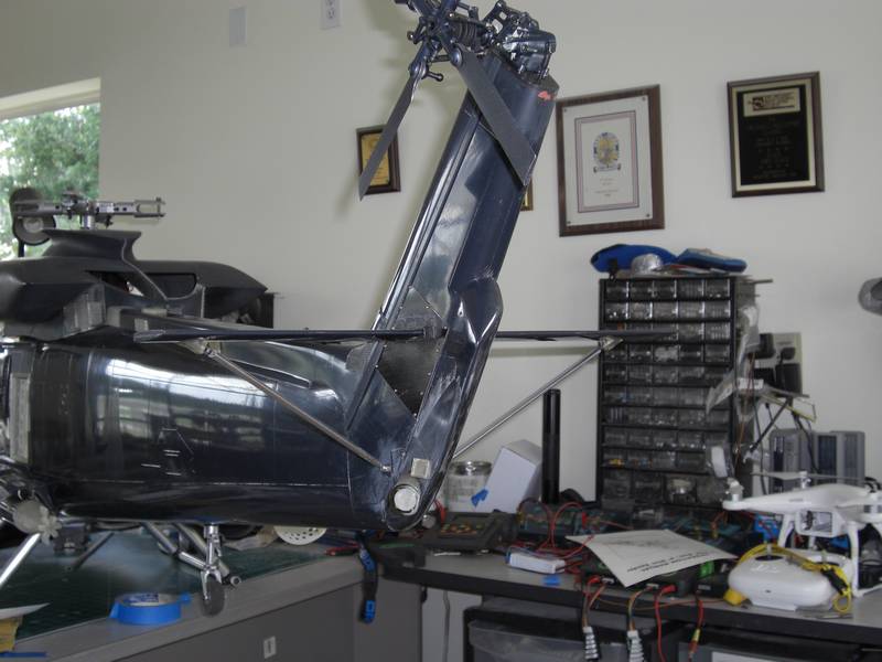
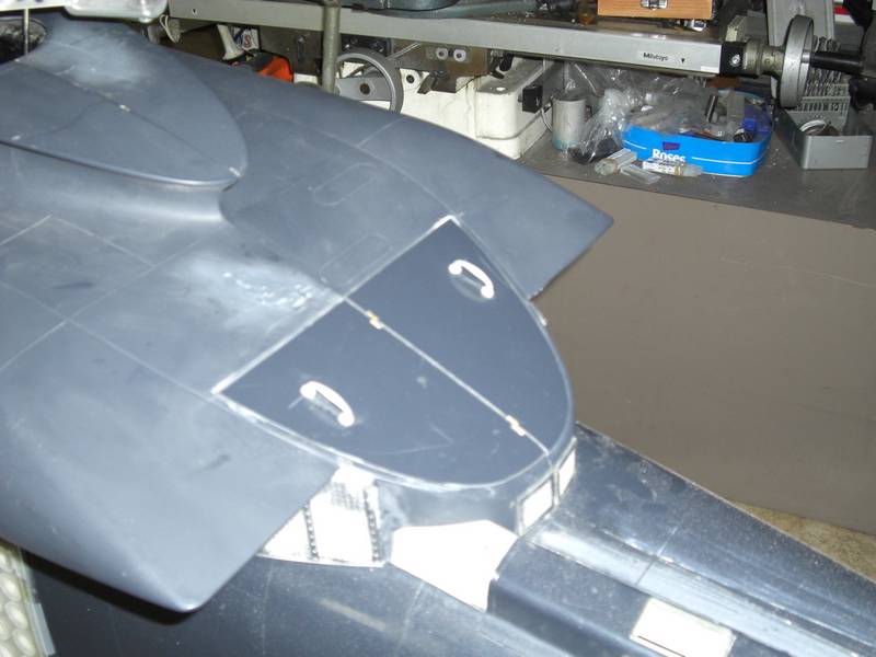
The next job is proving to be one of the more difficult alignment tasks as there are no straight lines or center lines to measure from. I am talking about the horizontal stabs of course. The only thing I can be sure of is the height , but the distance back and forth and the angle in and out has no defined points of reference. I would normally drill a hole and insert a CF rod and glue the stabs to the fin using the CF rod as an alignment tool. In this case, there is a panel on the port side which has to be removable for access to the tail servo and the tail servo sits exactly where the rod would go. To make matters worse, on the full size, the stabs are not fitted to the fin, but are spaced off on hinged mounts and the bracing struts (the next problem) are adjustable to get them horizontal. I have to make the stabs removeable for access to the tail drive and servo, and also for painting them as they are red and yellow striped. After a lot of trial and many errors, I got the stabs in the right position.
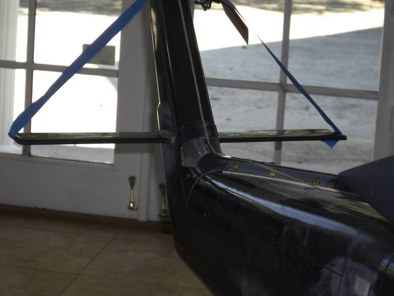
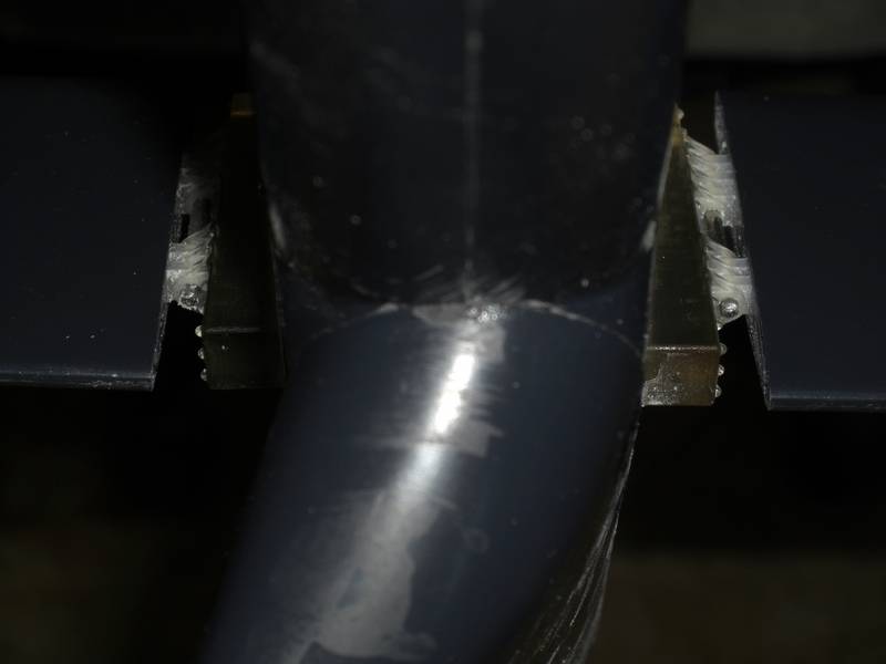
I printed up some sturdy hinge mounts, one side to go in the stab and the other to glue to the fin. I used a Vario push rod as a shaft to make the hinge through both mounts. Well, I gotta have one Vario part in it.
A bit more difficult to see from the end, but it shows the rod through the bearings.
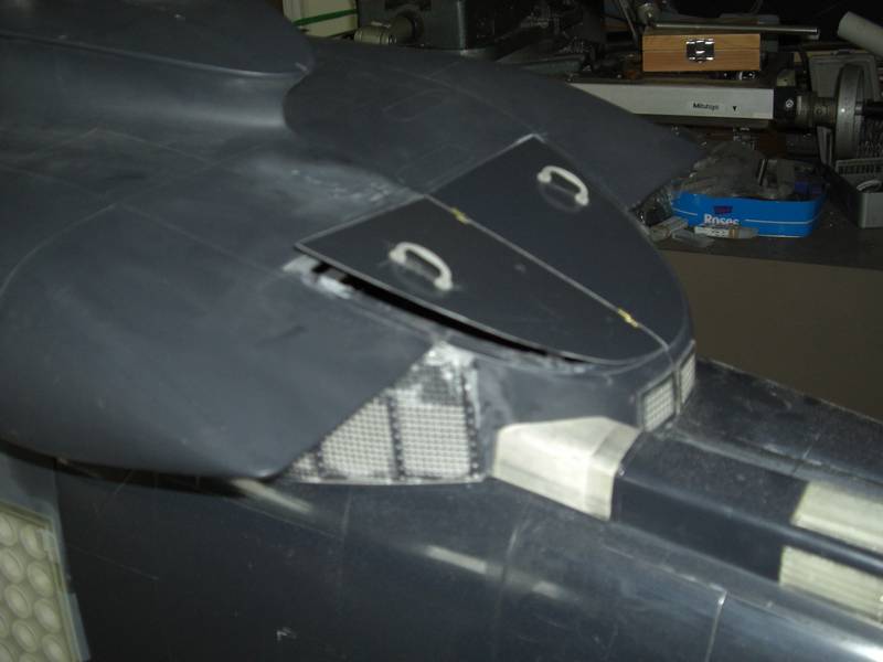
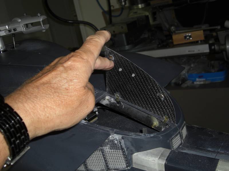
Carrying on with the difficulties of no reference points to accurately position things, the stab braces were next, but not last on that list.
It took a bit of juggling and tacking parts in place several times until it looked right. I made a slight deviation from scale with the under stab supports by making them solid instead of a flange. I could not figure out how I could tighten everything up with a flange so I took the easy way out.
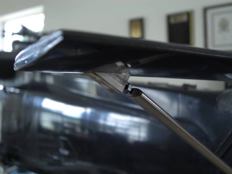
A small molding to fit exactly inside the aluminum tube was drilled for 3.5mm thread and a cut down 3.5mm bolt used to adjust the angle. The other end was similar, but I drilled the 3.5mm bolt down the middle and tapped it 2mm and found some 2mm rod ends on a rc car site. They were just right,so I printed up a mount and held it all together temporarily with a 2mm pin.
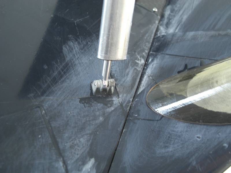
Next in my alignment problem came the doodads on the back of the fin. The photos were such that I could not get a direct measurement on anything both in size, position or angles. I spent a lot of time measuring different pictures and comparing the results until I got a good idea of what and where. This is one side. The end of the square thing actually plugs in as it will be painted red so I dont have to mask it off, I can paint it separately and then glue it in place
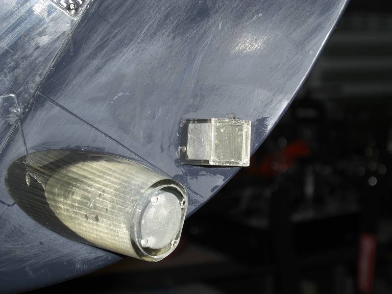
This is the other side
You notice all these protrusions point in different directions. Very difficult to get right. Anyway, thats the end of the big parts, now I have a myriad of small parts to make, like tie down rings and door runners. I won't document these as that would just fill up my web page with tiny details so the next update will be when I have started sanding and priming ready for paint.
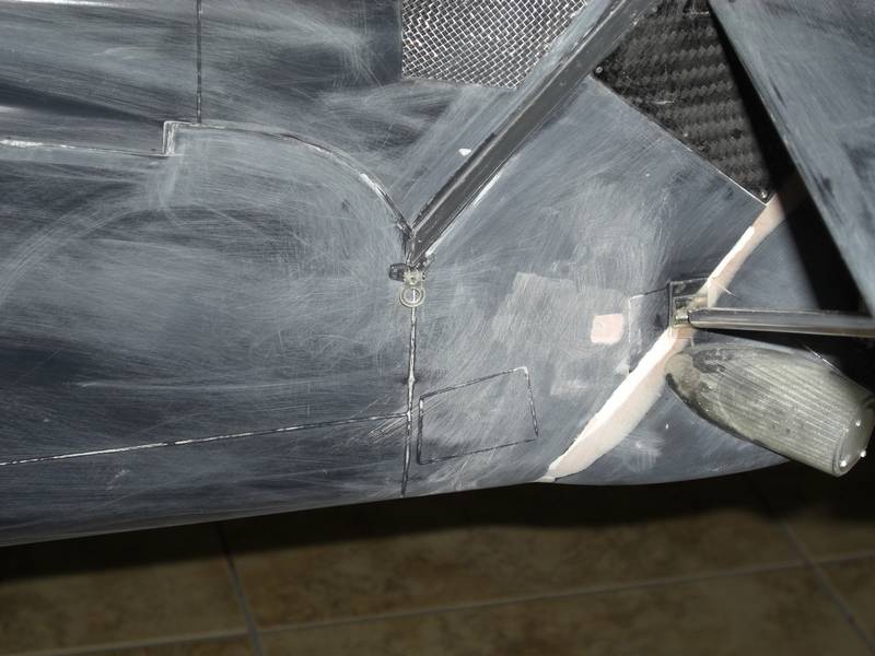
There was one large part which took quite a lot of making so I have taken a picture of that. Its the winch.
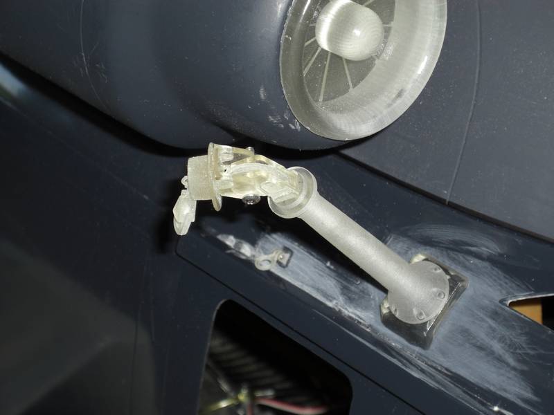
It is fitted together on pins so that it can be removed and painted separately. Also all of the parts swivel and the pulley rotates. The winch hook is secured with a bungee cord to the ring on the fuselage so that he crewman can open the door and release the winch if it is needed
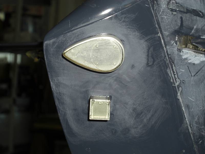
Its been a while and I have been working away on my printer turning out odd parts. However, some of them didn't neeed the printer, like the turbine exhausts
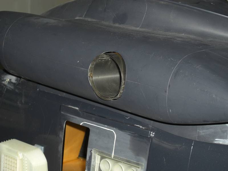
I spent a few minutes modifying some handles so they pierced the surface for the rear engine covers, but the covers themselves took most of the time to fit.
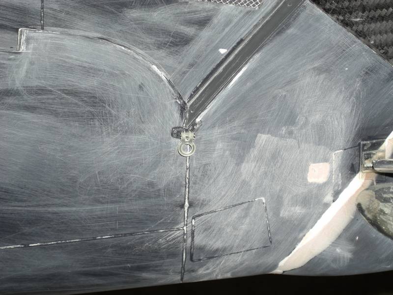
next was one of the mooring rings.I'm starting t o get to the limits of my printer and my fingers.
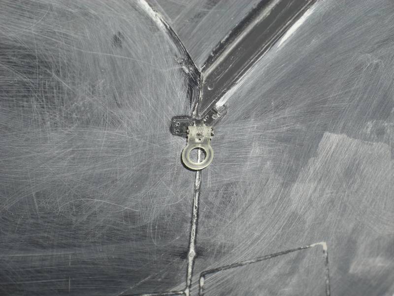
OK, a bit closer
Still cant see it?
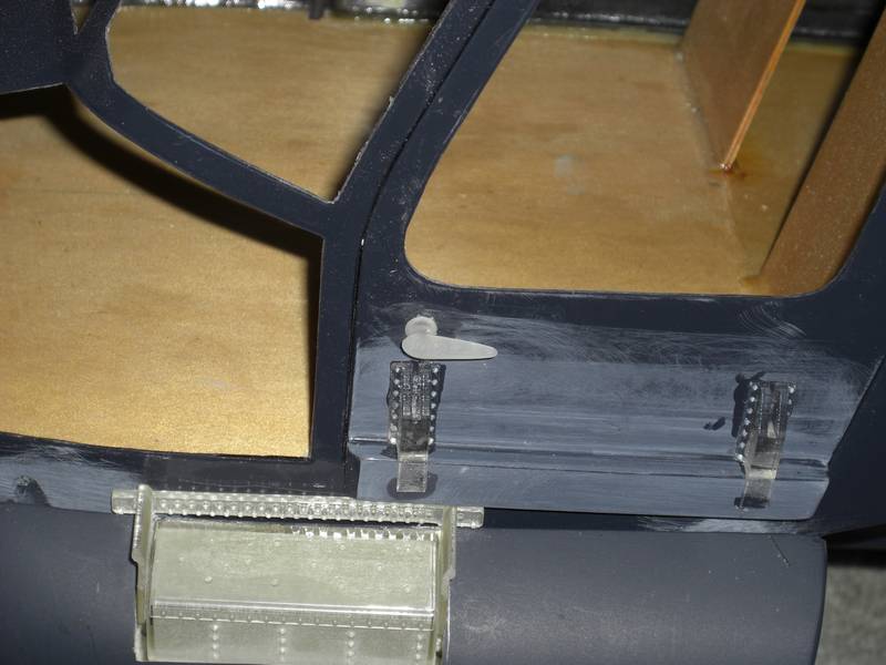
At the other end, I made some runners for the doors and some door handles. All small stuff that takes time.
Now, I am working on the cockpit and have started with the seats. There are a lot of challenges in the cockpit, so it may take some time to get anything ready to show.
As I said, It took a while to get anything to show. The first thing I did was to print up the instrument panel and individual instruments as they were different colors and it would be easier to paint the instruments black and then glue them into the gray panel.
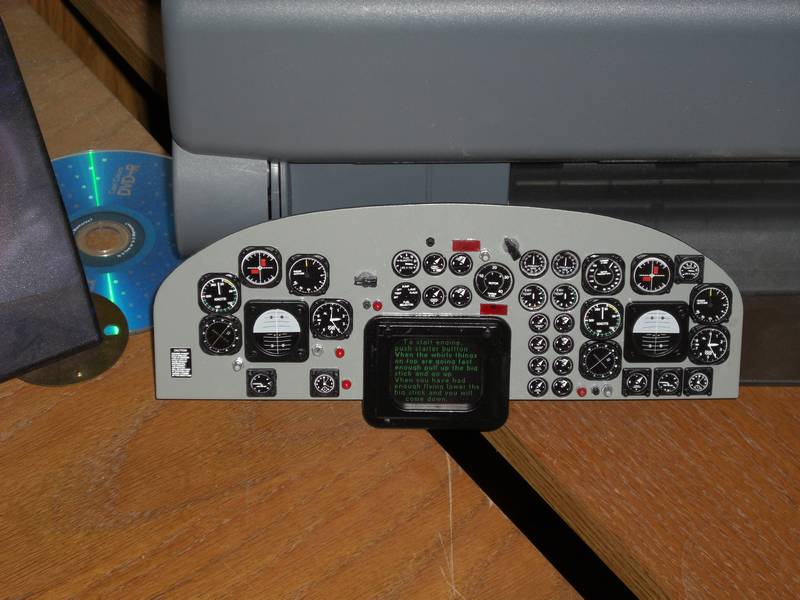
I bought a cheap display module and started to learn how to program it. The problem was that all I knew about what it displayed was data and as you will hardly be able to read it through the window, I just put some gibberish on it.
I made the mistake of making the shroud and painting it, then gluing it in place. Then I had to mask it off so I could paint the cockpit light gray
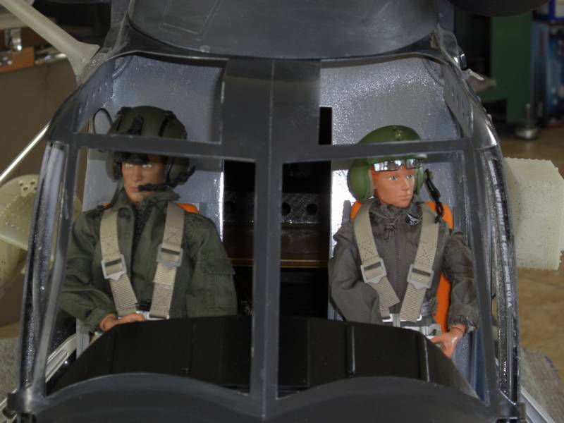
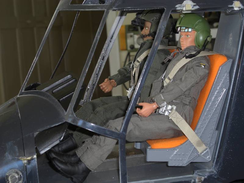
Then came the seats and their occupants. This is where I spent a lot of time getting the cushions just right. The seats on the full size dont touch the floor, they are bolted to the rear firewall so I did the same.
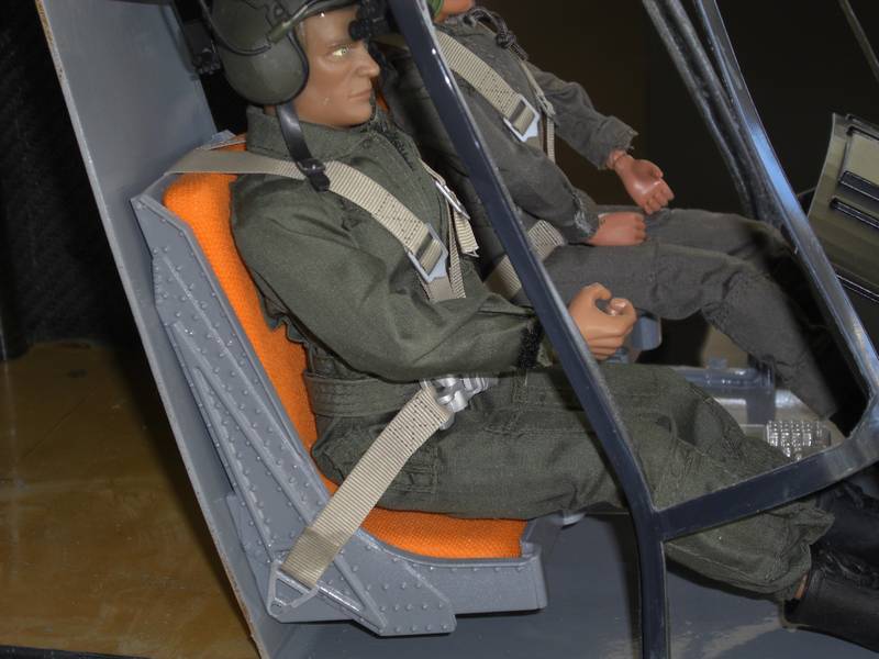
This is the side of the seat with the first few of the million or so rivets due on this heli. The seat belts on the full size are very wide so these are scale, but the buckles are too big. Maybe a change will be due later on.
And the lady co pilot gets her seat and cushion. I will have to find something to put in her hands as I have no idea if there is a second collective and where it should go. Cockpit pictures of the F model are very scarce and not very clear so the center console will be a challenge and a lot of imagination
After lots of burrowing around the internet I found some helpful pictures and set to on the center console
That is the result of 2 weeks work. OK, there were a few errors which needed correcting on previous versions so I had to make it more than once.
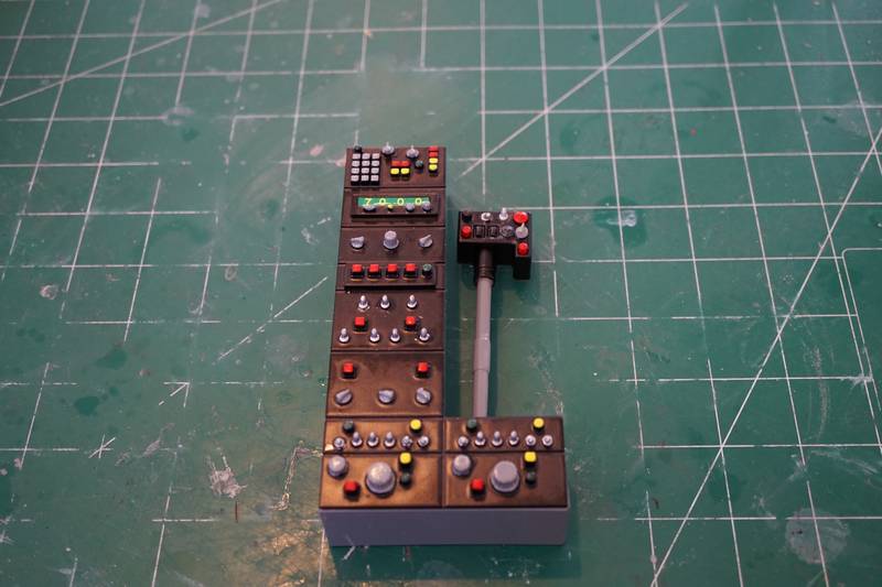
Then I found that there were 2 collectives and made up the box which sits on the end. All the knobs etc were individually printed and painted which made it a time consuming but satisfying job. Its a pity you will hardly be able to see it from outside the model, but I know its there. The collective for the right hand pilot comes out of the center console.
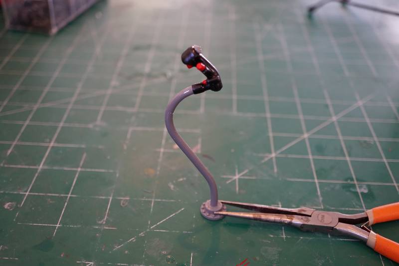
The cyclic was easier as Joe had taken a picture directly in the side of the cockpit so I could copy the curve directly into Solidworks. The handle with all the knobs and buttons was not so easy. All the different colored ones are made separately and painted and glued into place. It takes 3 days to do that, waiting for each coat of paint to fully dry before handling parts.
That is about it for printing up parts. Everything is done and the model is ready to be stripped down and primed ready for riveting. As this is a commonly done procedure I wont document each stage of it but there is one feature I will take photos of and describe as I get to it. It will be a while, so don't hold your breath.
I looked at the archives, and this month marks the end of 2 years on this build. I still have several months work left to do!