I ordered one of the first batch of Goblins and when it arrived I was once again impressed by the quality of the kit and the instructions. Everything went together smoothly and I fitted a V-bar stabilization system, which was another thing which impressed me. It was very simple to set up and had commands which made sense. It did not have the versatility or tuneability of the Helicommand, but for an SAS novice like myself, that was a good thing. I flew the helicopter and liked the smoothness but to get the thing to stop wobbling I had to run the head speed at 2300 rpm. Having just finished my 300C and got it flying at 900 rpm, 2300 made me cross my legs. A little work on the head, a change of pulley and a reprogram of the Roxxy ESC had it running at a more comfortable 1700 rpm and it was very very smooth. I liked it so much I decided to keep it and buy another for developing into a scale project.
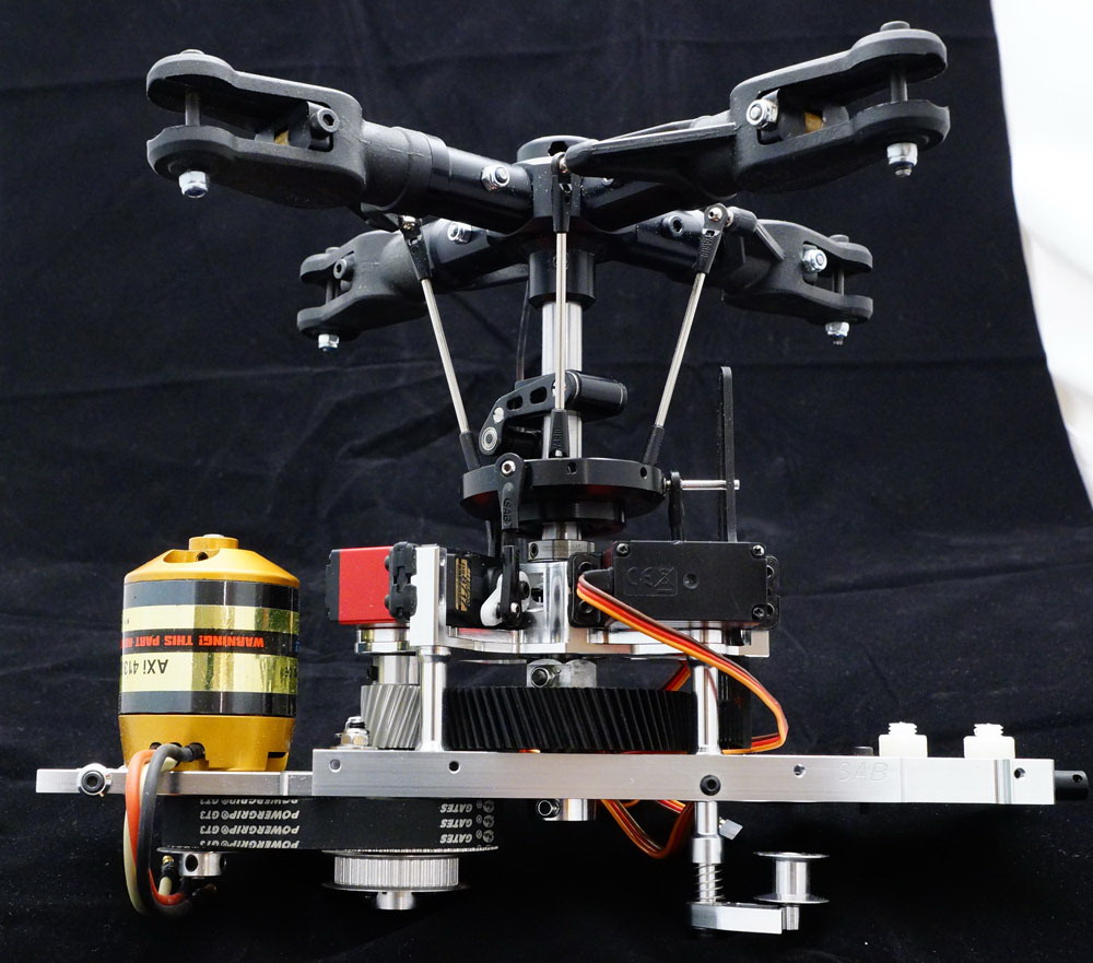
I built up the basic mechanics and then set to making a new main shaft to take the OF rotor head and swash driver. The OF swashplate was exactly the right size for the Goblin and the pushrods were nice and vertical.
Fitting a 300kv AXI motor and a smaller pulley gave me the choice of 1500 rpm or 1600 rpm on the head and I found that the model flew beautifully at the 1500 rpm setting.
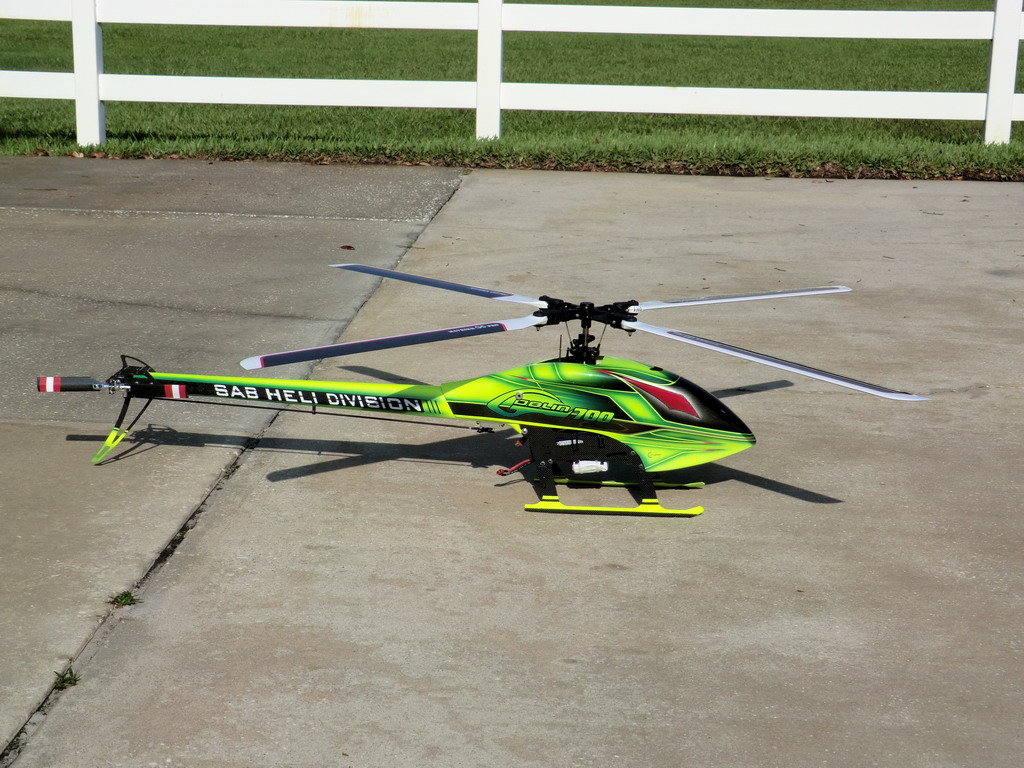
The only problem I had was spooling up as the thin skids had no grip on the concrete and it was like spooling up a heli on floats on water. So I had to do it manually and very gently but once up to speed the heli just sat in the hover and stayed there. So the easy bit was a success. Next comes the harder part of making a tail drive which can be adapted to either belt drive or shaft drive, and of course, a tail rotor gear box is needed. I have a feeling the 3D printer is going to get used for its intended purpose of rapid prototyping.
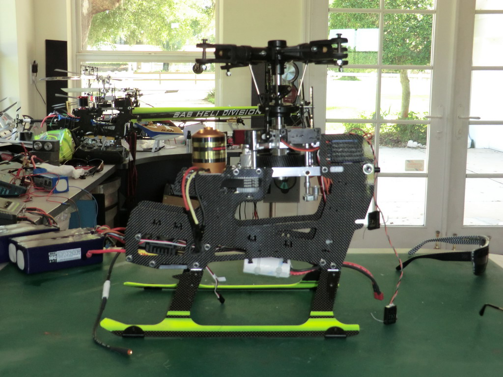
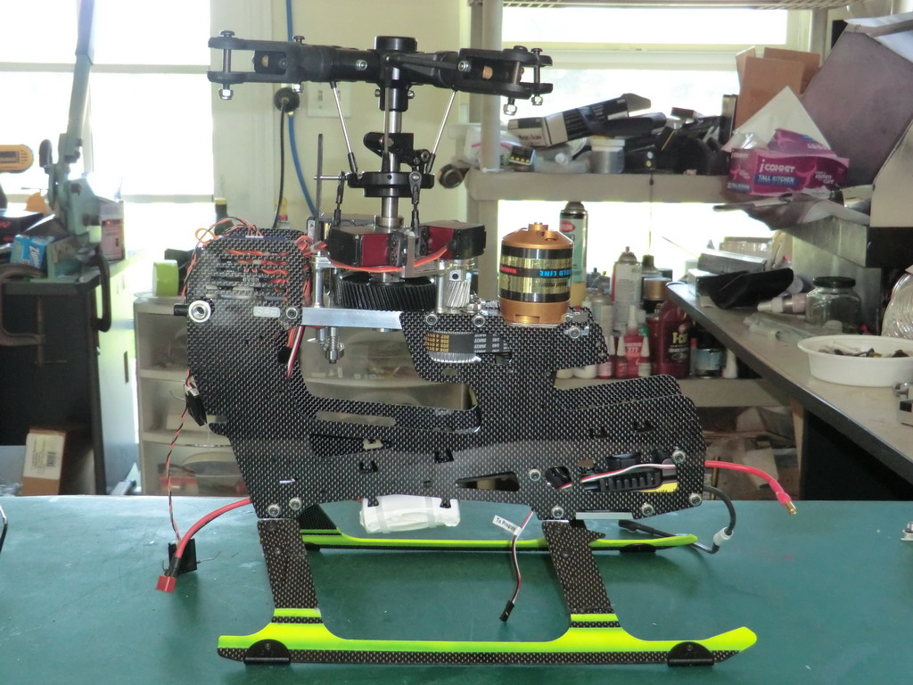
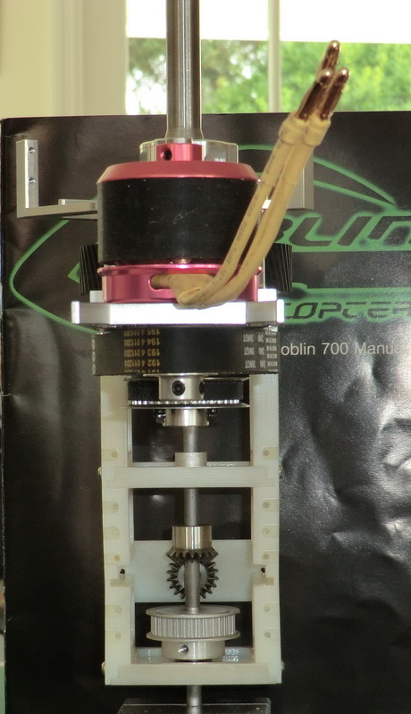
As I suspected, the 3D printer came into its own with this project. Everything is made in plastic before committing to aluminum. It even formed the threads in the screw holes
This is the final assembly ready for CNC machining.
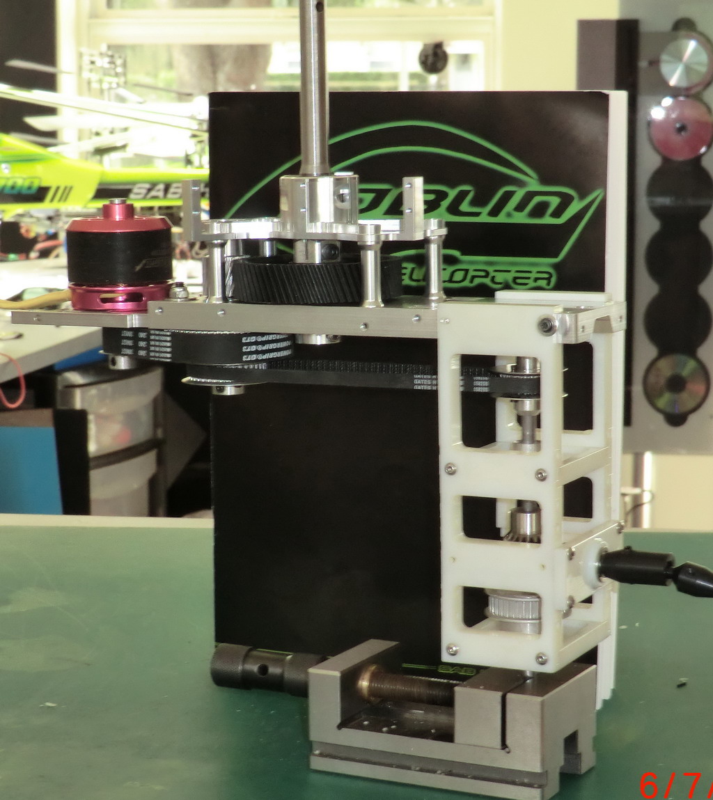
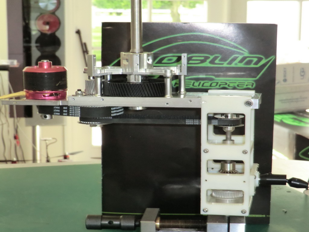
Several things to note
1) By chnaging the motor pulley and the motor Kv, virtually any head speed can be achieved
2) By changing the drive pulleys a wide range of tail rotor speed can be achieved
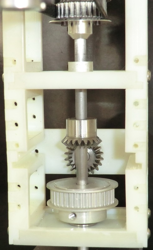
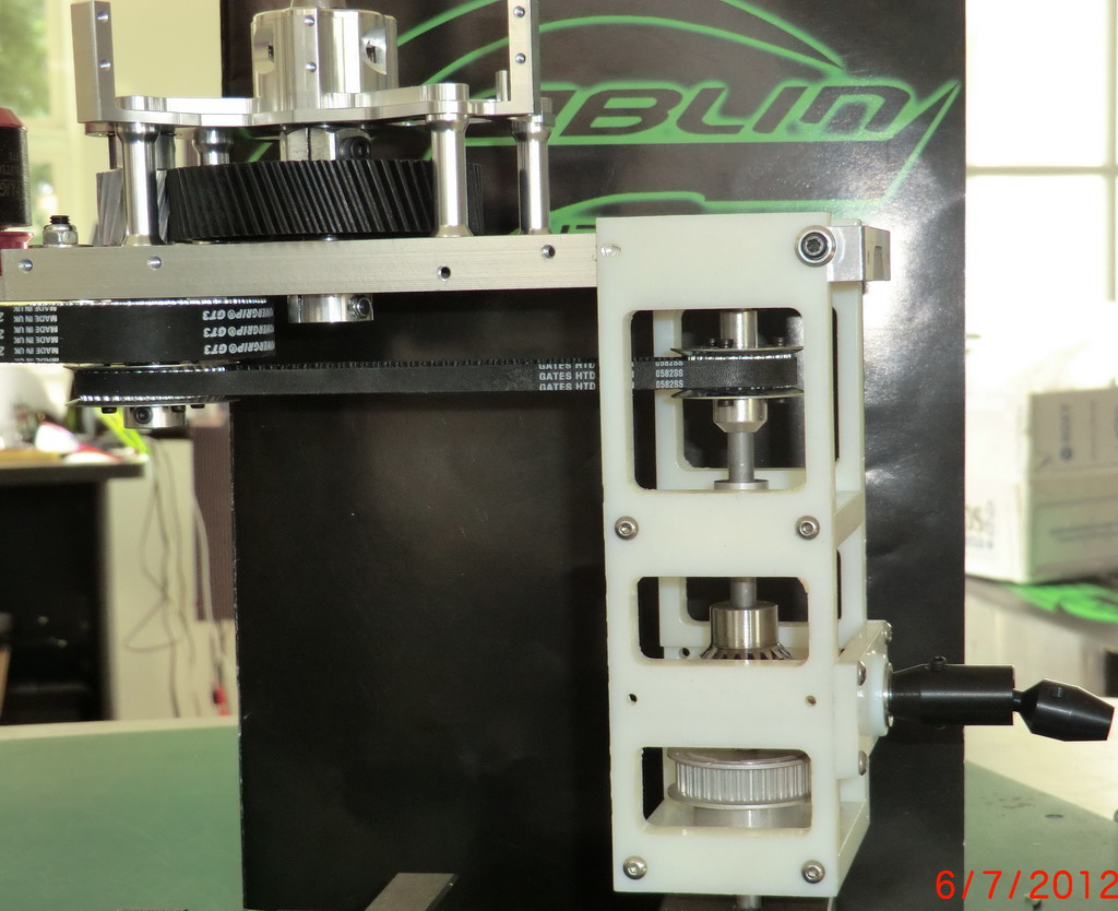
3) You have a choice of belt drive to the tail or via steel gears, torque tube drive to the tail
4) The pulley can be placed at any height on the lay shaft. A horizontal bearing holder can be simply left out if it is in the way
5) There are a lot of threaded holes in the edges of the side panels to allow the position of the torque tube output shaft to to placed in several locations, but the actual position is not vital due to the dog bone couple being able to take a wide angle to the drive shaft
6) If the side panels are too tall, they have been machine so that the wall is very thin under the horizontal bearing plated and a couple of minutes workwith a dremel or hacksaw can remove the excess as long as there is one on the bottom of what ever is left it will be strong enough