Kamov KA 50
A German gentleman by the name of Volker Jung has created a set of mechanics for the KA-50. For those of you not familiar with this machine, it has twin contra rotating rotors one over the other, a bit like a piccoo z, although I cant imagine anything more different. When I saw the mechanics flying I was very impressed and ordered a set. For those of you thinking of joining in, start at about $7500 for the mechanics, $6000 for a turbine and some stuff to put in it. Then there is the body kit, but that is coming later
I ordered the mechanics in April with a delivery date of July. That slipped until September but it was no biggie as I was involved in so many other things that it was not until today that I actually started on it. Thats Dec 16th. Yes, I am a patient man. When my favorite oak tree blew over in hurricane Katrina, I planted an acorn am am patinetly waiting.....
The instructions are all in German, with a google transdlated English set which dont help much , but fortunately the manual has excelent photos of the assembly and some of the hard parts are already done. As far as i can see I have a 200mm mainshaft, a 15mm mainshafy inner and a 2.4 m 3 blade rotor head twice. Should be fun. OK, on to the assembly, but be warned, I am waiting for parts for the Blackhawk so when they arrive I will put this to one side and get on with that.....ok who am I kidding.
Step one, fit the circlip and screw the bottom plate on.
That wasn't too hard was it. I have a feeling I am being started off easy and it will get more difficult later.
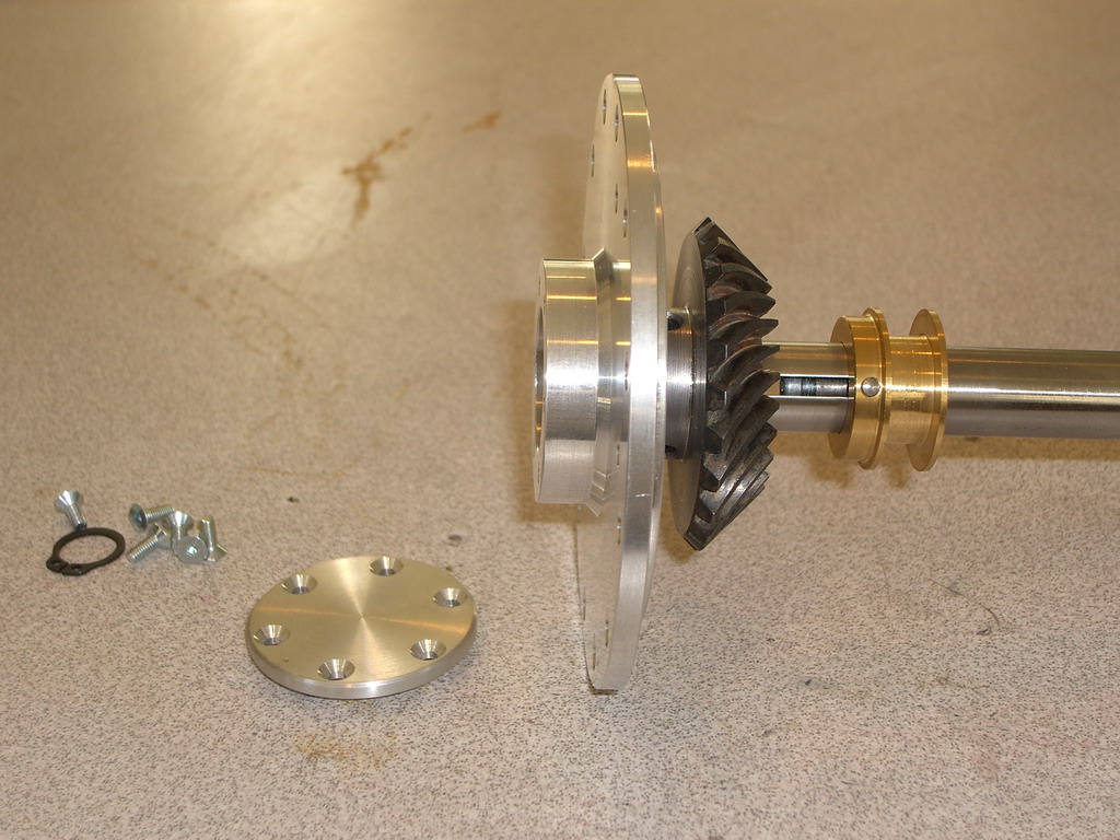
Step 2, shove that thing carefully through the hole. Its an oil seal so dont tear it.
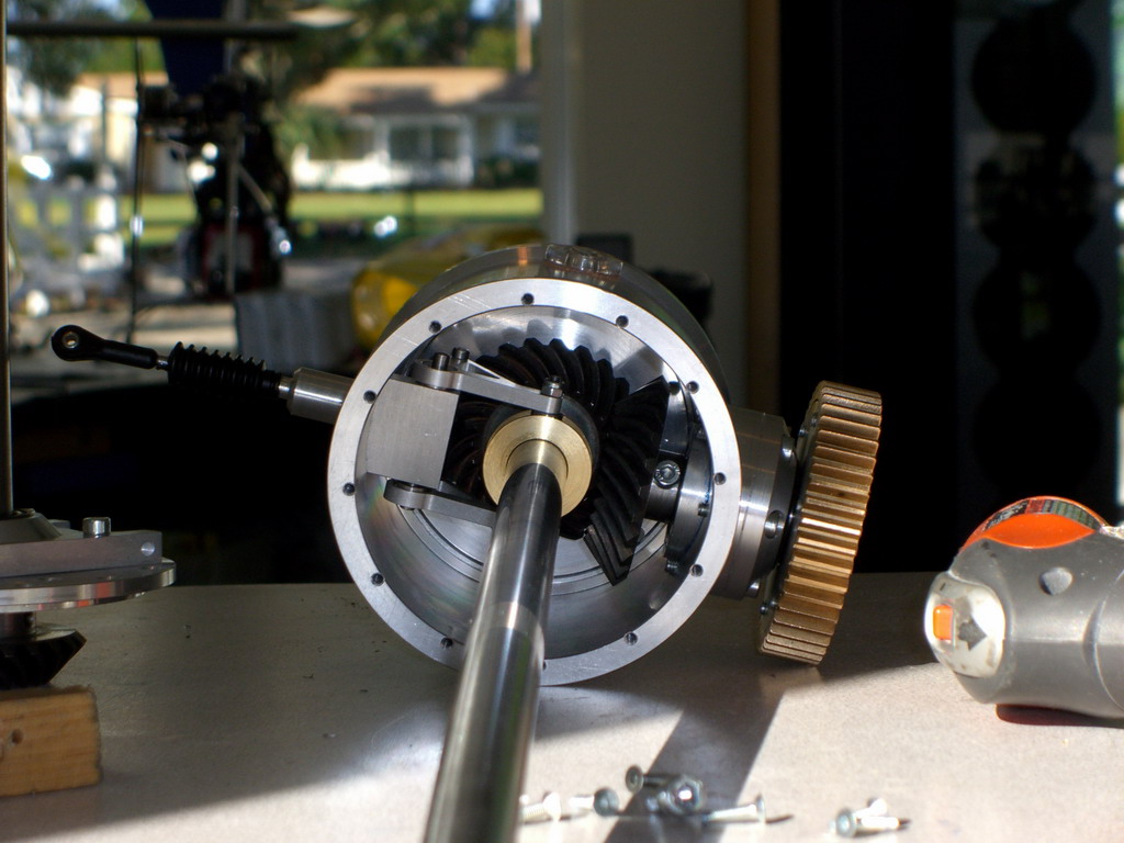
So far so good. This is how it goes together. The brass piece with the groove is connected to the 6mm pushrod which goes right up through the center mainmast and will be used to al;ter the pitches for rudder control. More on that when we get there
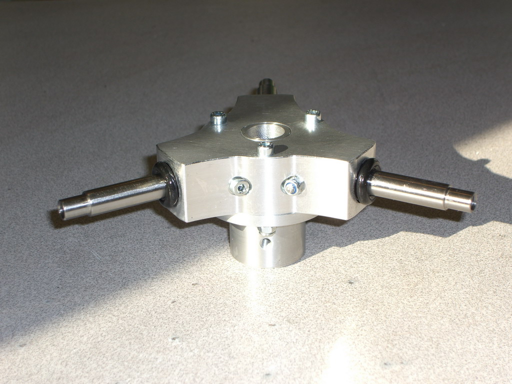
This is the tail rotor pitch adjuster! Well it makes the tail swing round. I actually had to build that, most of the rest of it was preassembled, thankfully.
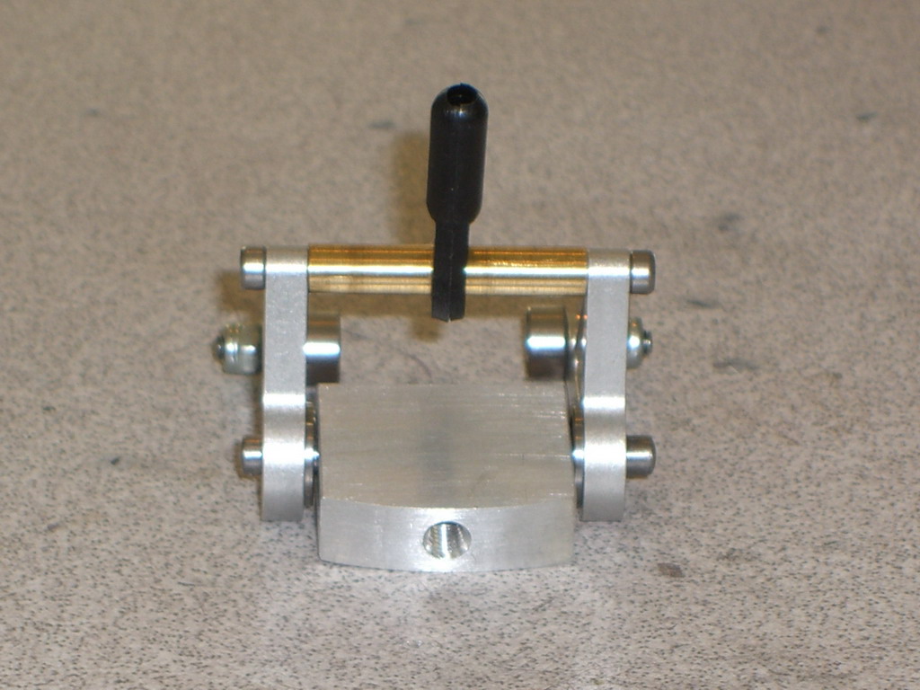
That gets fitted inside so the 2 bearings run the brass groove and a pushrod comes out through the side. The rubber bellows is needed to keep the oil inside this gearbox as it is constantly immersed in oil.
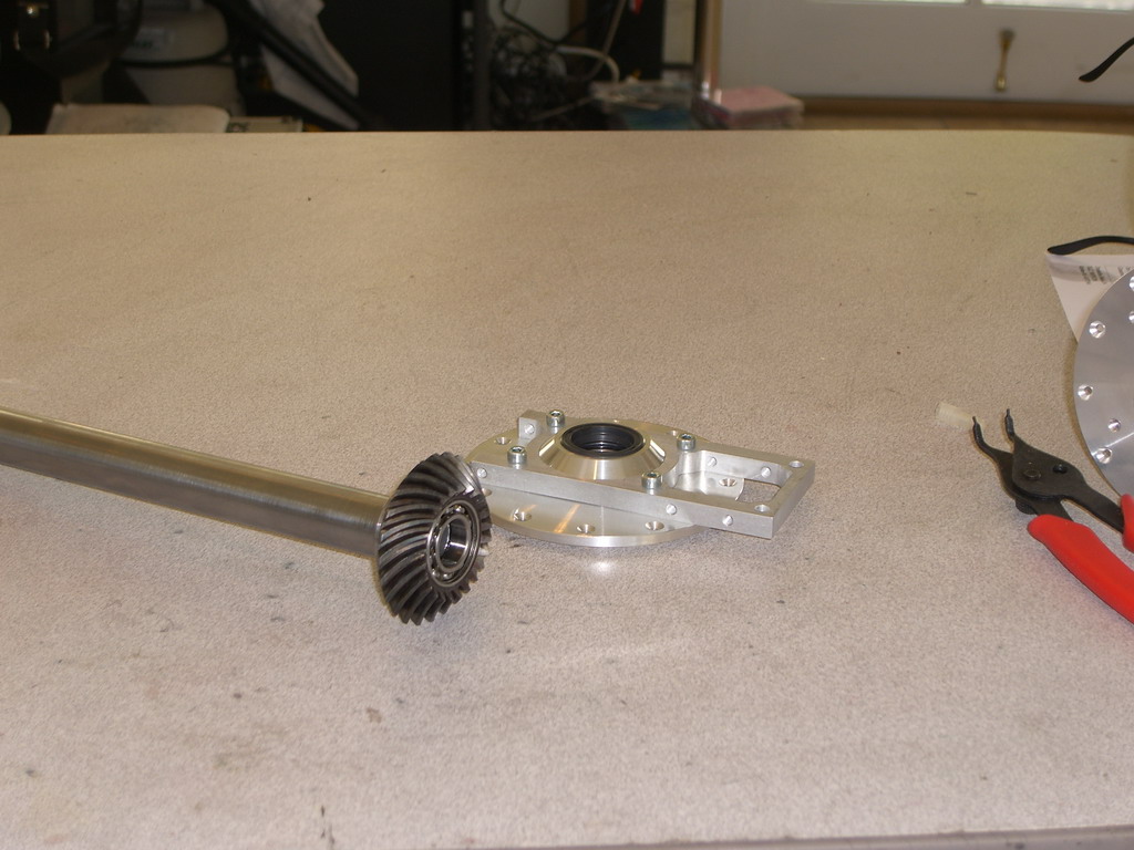
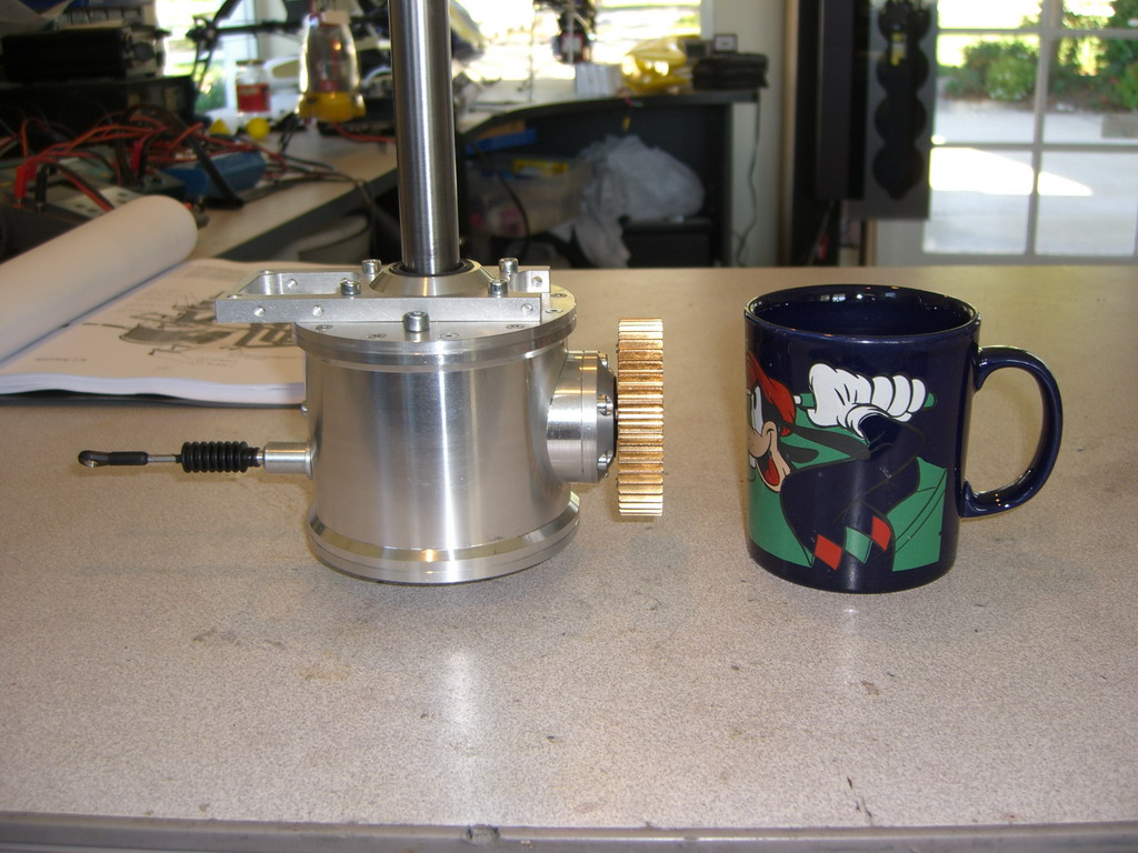
Now you can see how it goes together. Hopefully this is the last ime I'll see this, unless I put it together wrong

And here is a picture of it all together with my tea mug for size comparison.
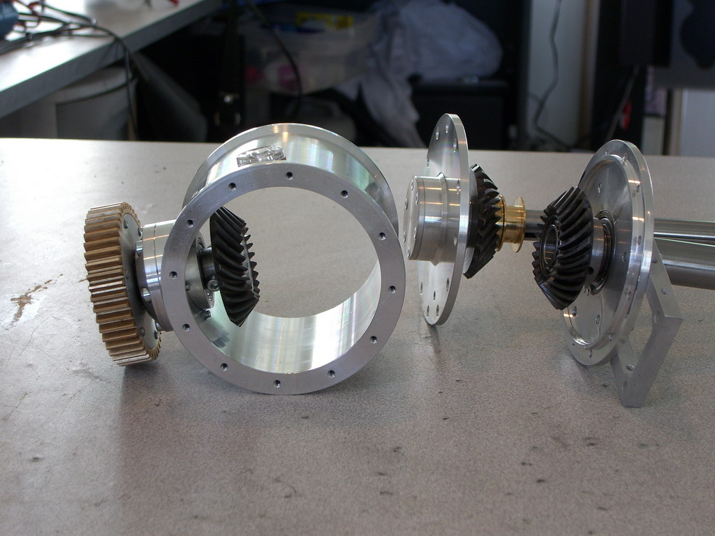
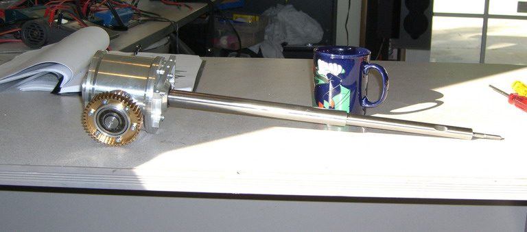
And to give you an idea of the size here it is on its side. Wait til you see the swashplates and rotor heads!
Add the frames with bell cranks
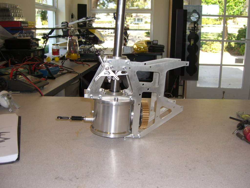
And then build and fit the transmission. This is a multi reduction system and each gear train has to run smooth with a tiny amount of backlash. Couple that to misaligned and poorly tapped holes and you can tell it took more than a couple of minutes to do
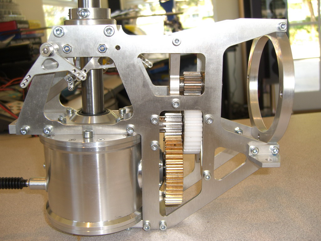
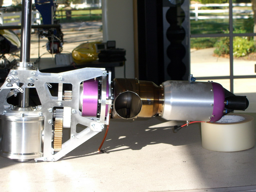
Then the turbine needed to be fitted, only I didn't know there was a special one for this heli. Anyway, I soon had this one sorted and it fits perfectly, except one spacer is missing so I guess I will be making one of those tomorrow.
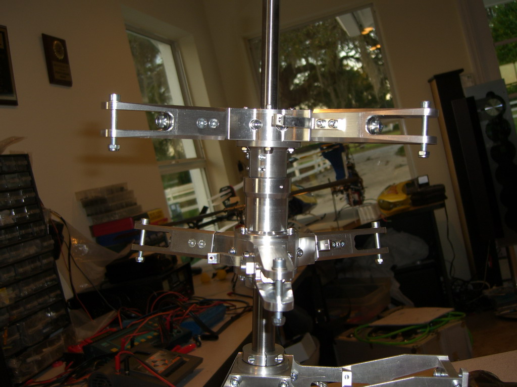
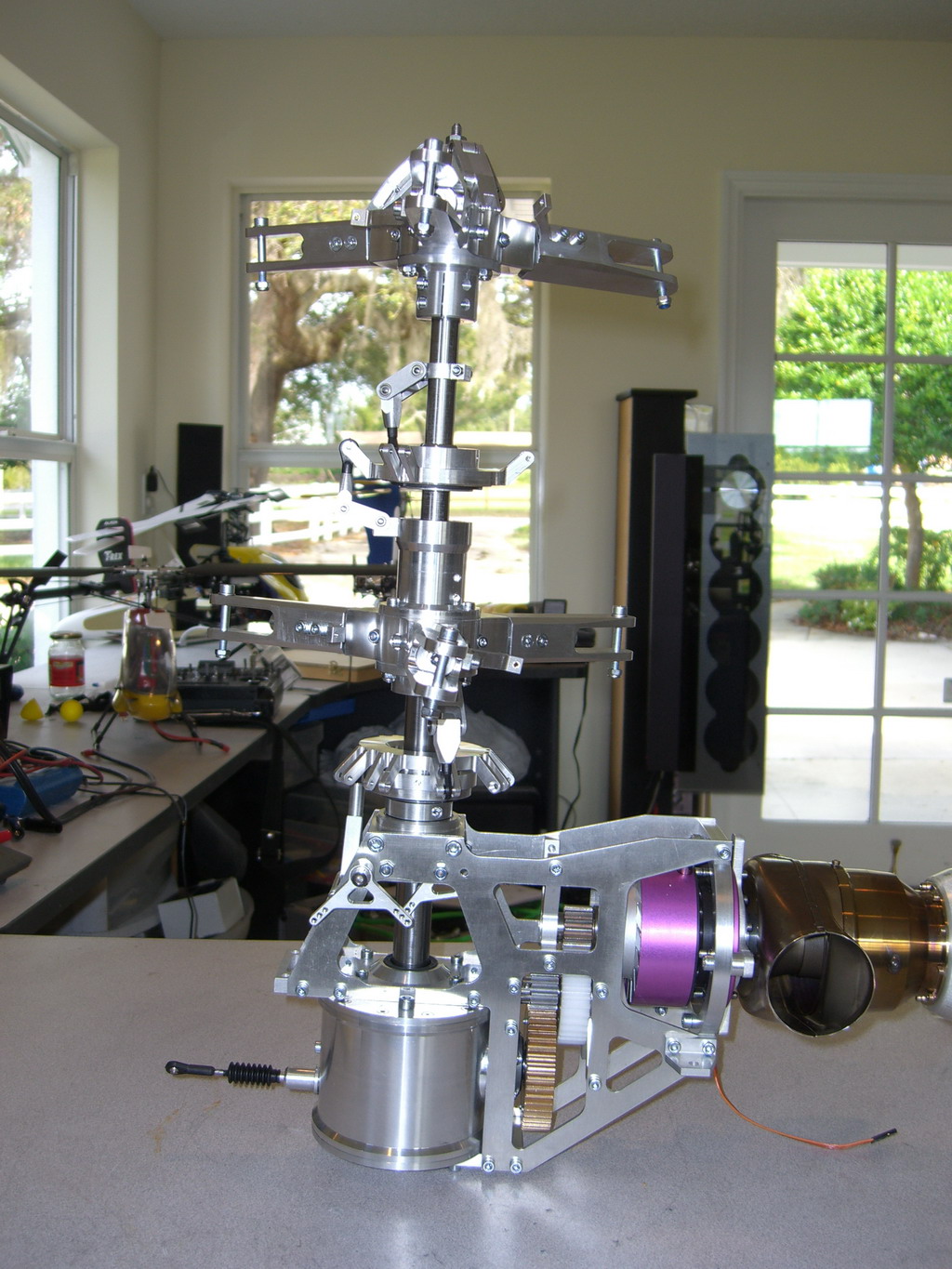
Now I get to put that all to one side while I make up the rotor heads. This is the top one and the bottom is the same except it has a bearing in the hub.
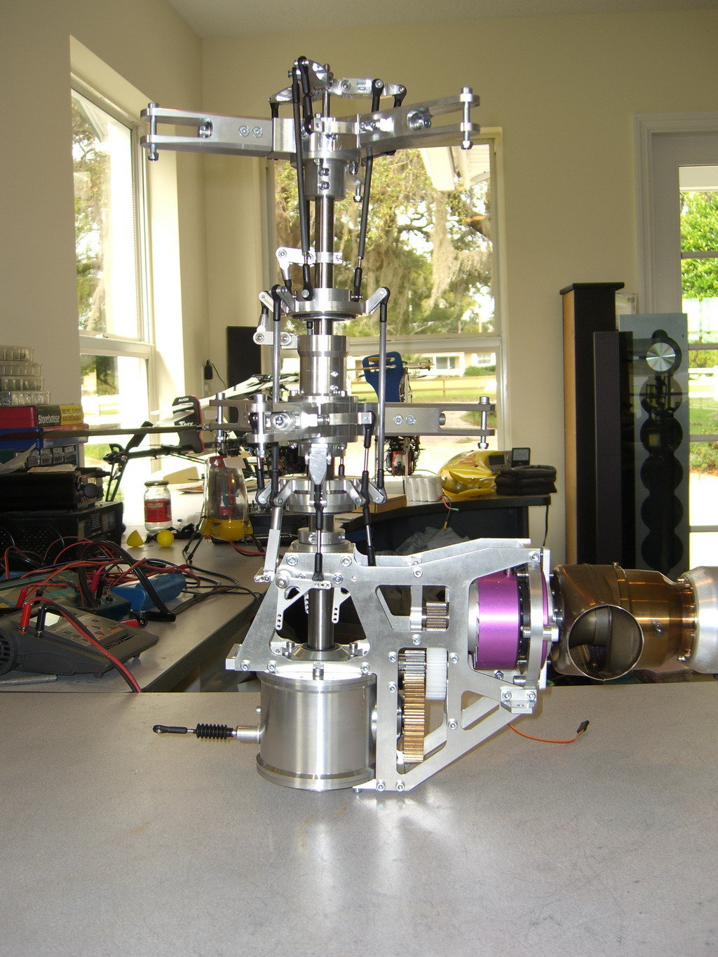
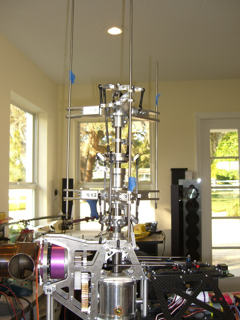
I slipped them both on the mast, impressive aren't they? Enough for today, swashplates and other stuff tomorrow.
The swashplates came ready assembled. The next step was the anti rotation brackets and the doodad on the top which alters the pitches to allow tail control. Once these were done, I loosely assembled the lot.
Then I had to start making up the links, but just look at this ball link. It sits flush up against whatever it is controlling and the countersunk screw wont allow the link to leave the ball. Superb. I gotta find out where they come from for future big models.
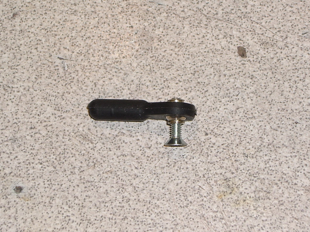
Then the simple job of fitting all the links!
Everything is loosely set up and there are some drawings with dimensions so tomorrow I will get to the set up stage....well maybe not cos today a motor arrived which is perfect for the Blackhawk tail. Then the lathe broke down while I was nearly finished making a tail pitch slider. Yes, I know, more excuses.
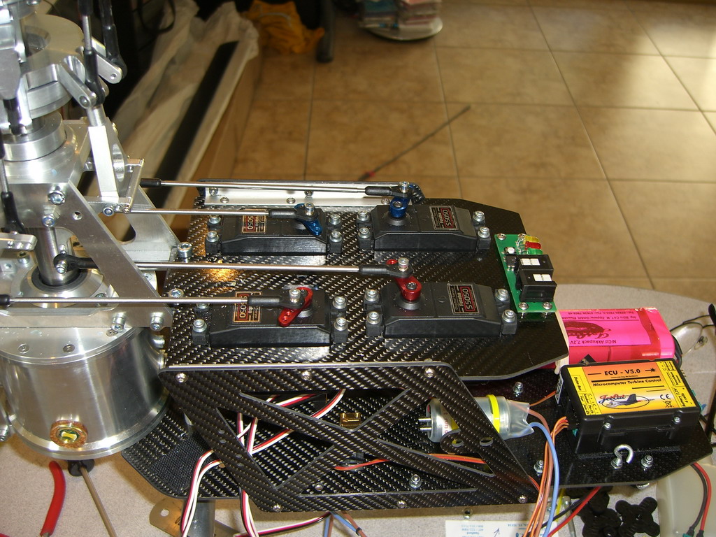
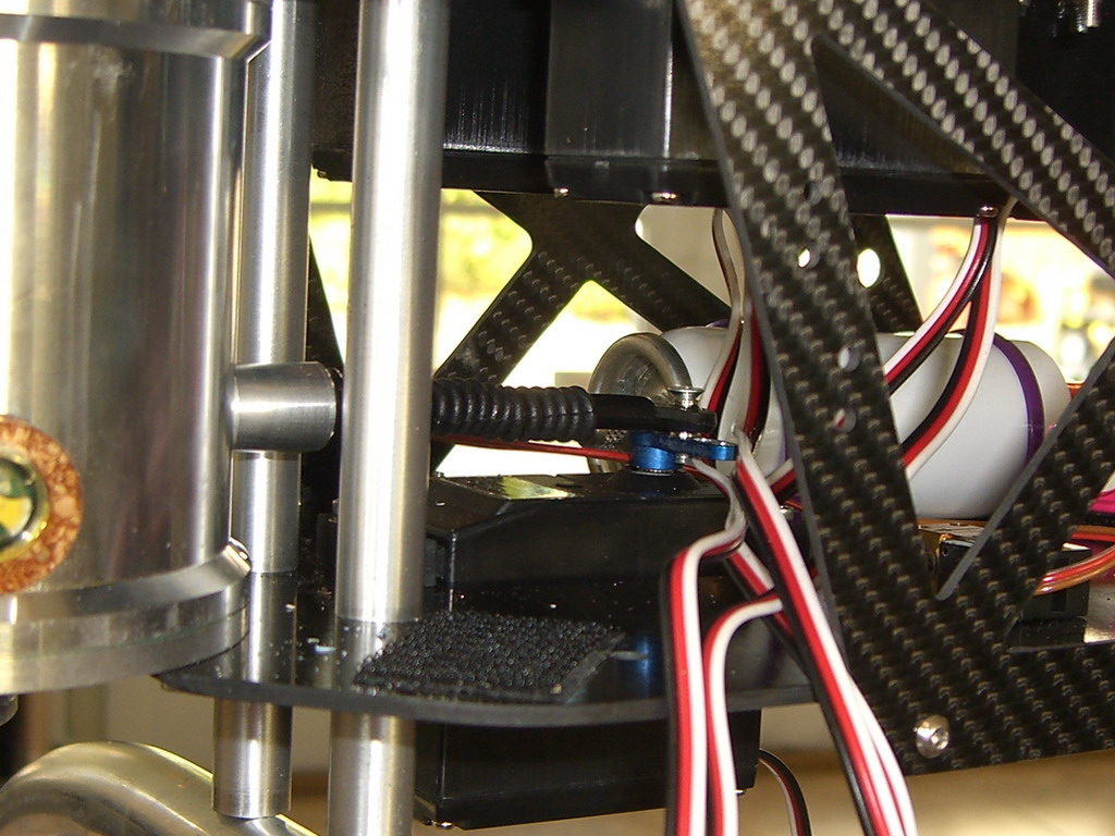
I built up the two avionics trays and mounted the botrtom one permanently and the top one temporarily. To be honest, I was itching to see how this thing worked. After a whole day messing with it, I still dont understand it but its looking good.
OK, on to the set up. The instructions say get the rod lengths accurate to 0.5mm so I did. That was a waste of time. First job was to set the "rudder" servo at mid travel and then set the linkage so it was in the middle of its travel. Thats the bit with the bellows on it.
Then I set the swashplate level all round by adjusting the servo centering on my Tx until my test block was dead smooth all the way round, on the bottom swash only of course. Then comes the tricky bit. Ever set your linkages up like this?
Its a first for me. The top rotor head becomes the master. The bottom one can be rotated and is locked in place at the right position later.
The top one is adjusted for zero pitch with the Tx. Both sets of blade holders are now aligned one on top of the other by turning them. One blade holder is selected as the master and the pitch angle of the top rotor is adjusted so the rod drops into the bottom blade holder and is absolutely parallel to the mainmast. The pitch of the bottom blade holder is adjusted so that the rod drops through smoothly. This means both of these blade holders are at zero degrees of pitch Then the other top blade holders are adjusted so their rods drop into the top hole on the bottom blade holders and then the bottom blade holders pitches are adjust so the rods drop through smoothly. Now all 6 blade holders have exactly the same pitch at zero degrees.Well that was a waste of time, but all is good as I have it flying. The secret is in the mix, only one and its from the gyro to the pitch. As the collective is moved one way, the pitch on the bottom rotor changes one way and the top rotor the other way, but by twice as much! This introduces yaw, the gyro senses it and reduces the pitch on the top rotor to keep the thing fram yawing. If its not yawing, it should be at the same height. A yaw command increase the pitch on one rotor, and reduces it on the other by the same amount. Very clever and very simple.
The first flight video is here Kamov first flight