Mil MI-8
First a little background. I saw this guy on SRCH building an MI-8 from scratch. His bio said he was in Nigeria so I simply watched as he progressed. Then the thread stopped. I liked his work so much I wanted one, but Nigeria? No way.
Fast forward a couple of months to December when I was at OHB. I saw a gorgeous 5 blade head on Esprit model stand and took some photos. Someone on SRCH asked about rotor heads and I mentioned these and put up the pictures. Well, they wanted o know where they were from and who made them. I was using a very high resolution camera and was able to expand the picture out so the manufacturers logo was visible and I posted that. Off they went searching for it and found a web site with the head on it. So I went and looked and sure enough, there was the head, and to my amazement, there was the MI-8 in kit form for sale. So I ordered one!In January a box arrived with this in it, among other things
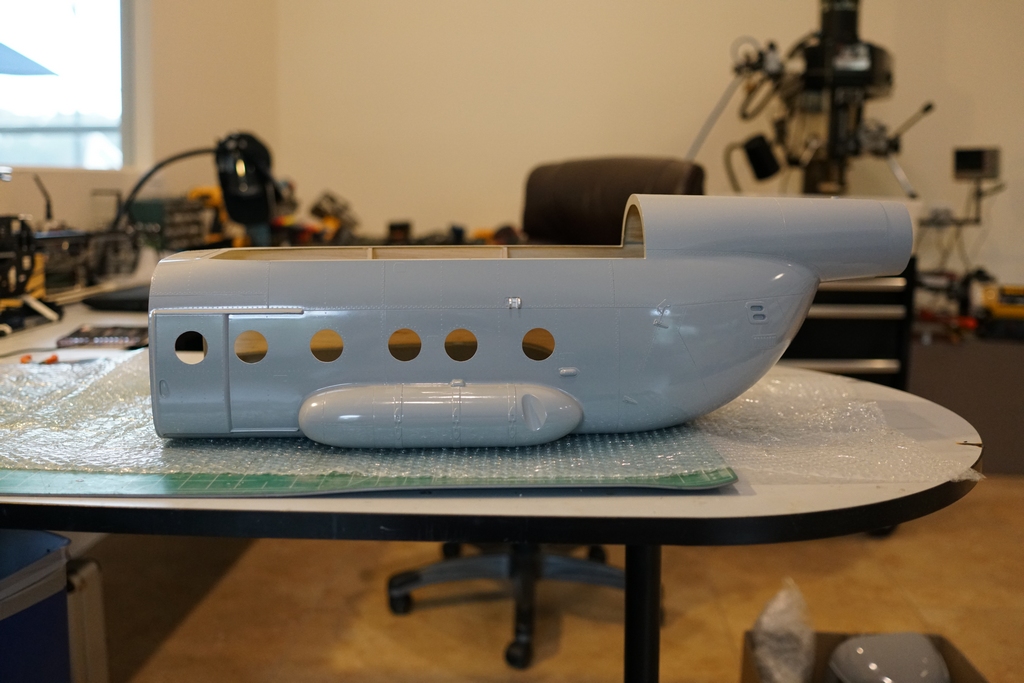
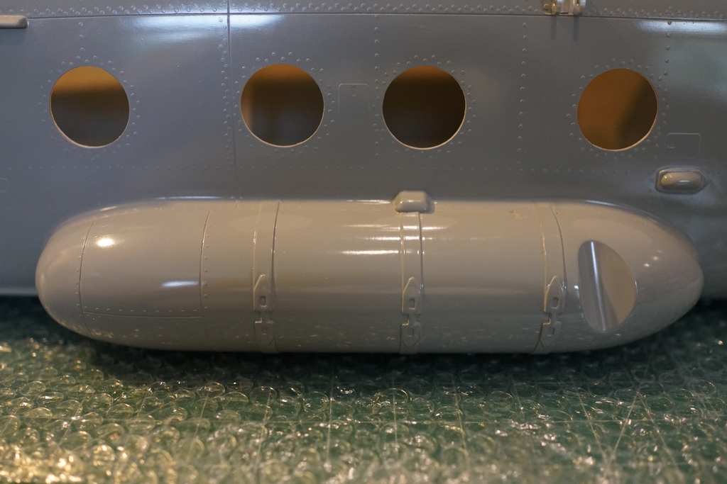
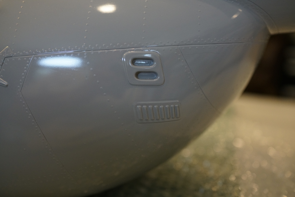
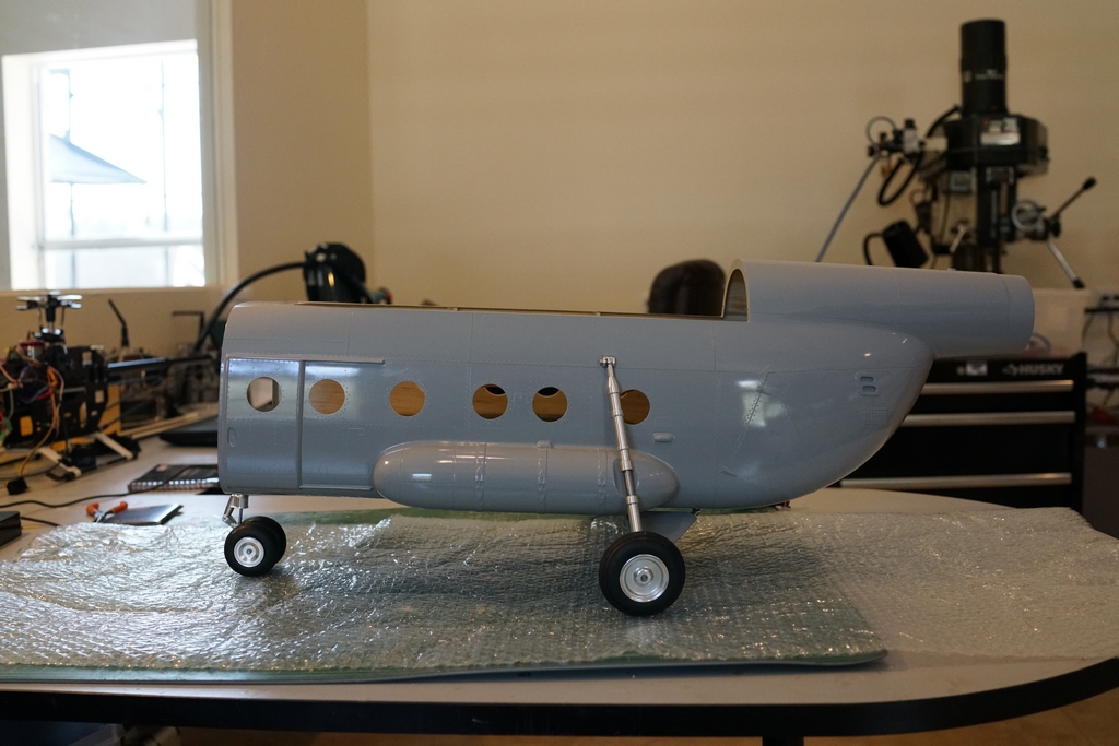
The level of detail molded in was astonishing, especially after just finishing a Vario EC135
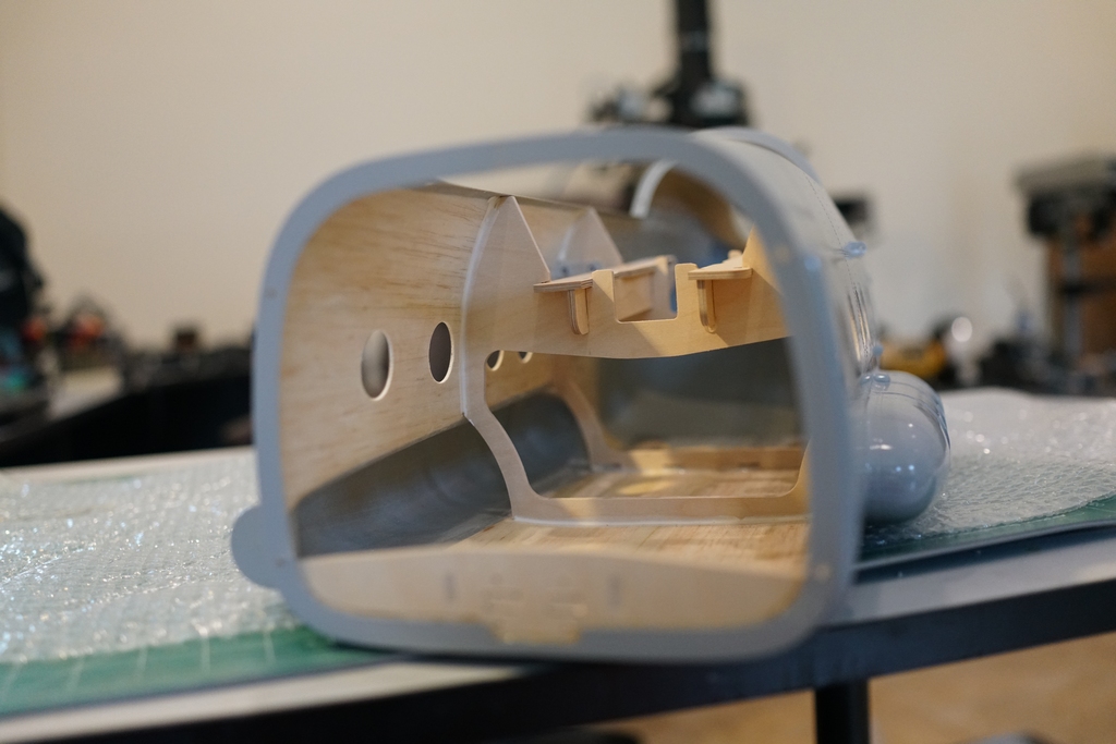
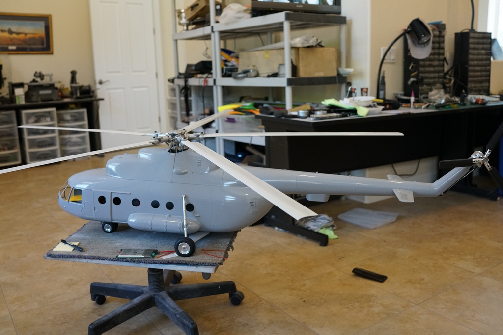
I had to hide it until I had the 135 finished and flying, but a couple of days ago, I dug it out of the trailer and started looking at it. I had some very detailed instructions which even had words in English on them which explained to me the assembly of the woodwork jigsaw puzzle. A little more background here. The manufacturer, Michael, designed this model around the Goblin mechanics. He was having his own version of the shaft drive conversion made, similar in design to mine. The main difference was in that he was modifying the Goblin and getting the conversion to be as wide as the Goblin chassis. My conversion bolted on to the side of the chassis and was therefore wider at the back end. Back to the woodwork.
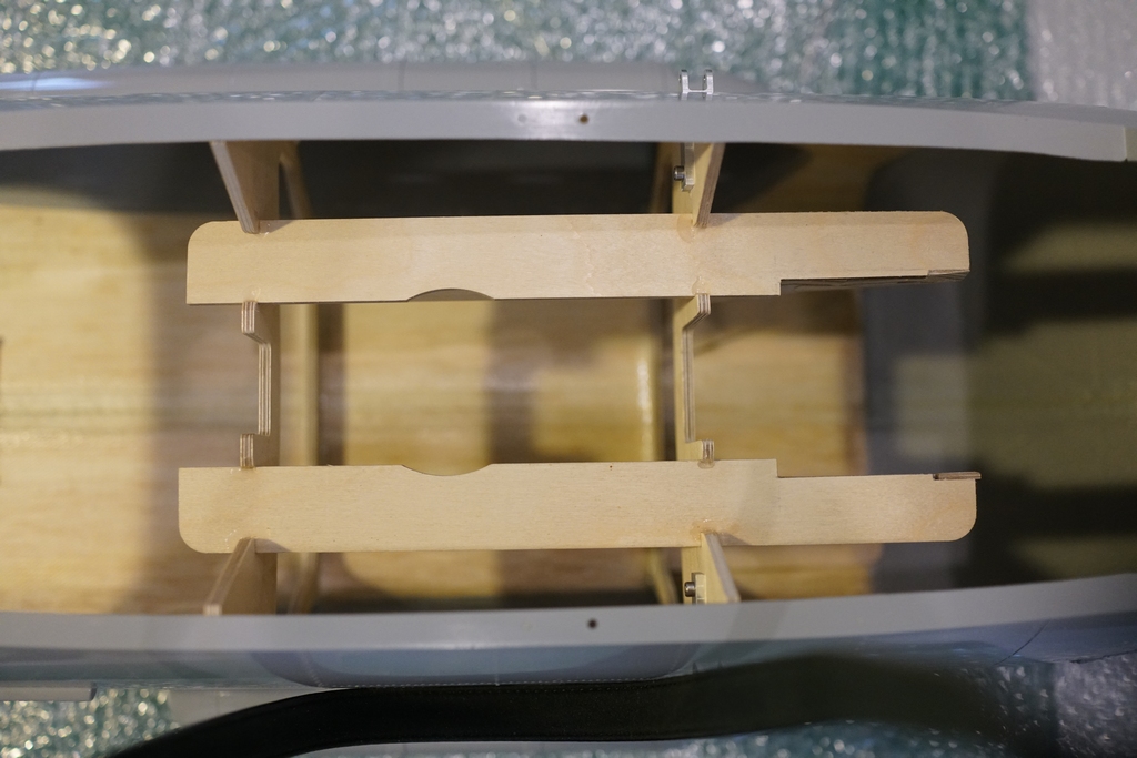
I had to widen the gap at the back so my mechanics would fit. I did fit another brace underneath to add support. The woodwork itself was amazing. All cut out for me, fitted exactly with no sanding and it clicked together like an erector set. Note the two pieces of aluminum bolted top and bottom of the rear bulkhead. They fitted through pre cut square holes and perfectly lined up the rear bulk head. They are for mounting the rear landing gear. More on that later.
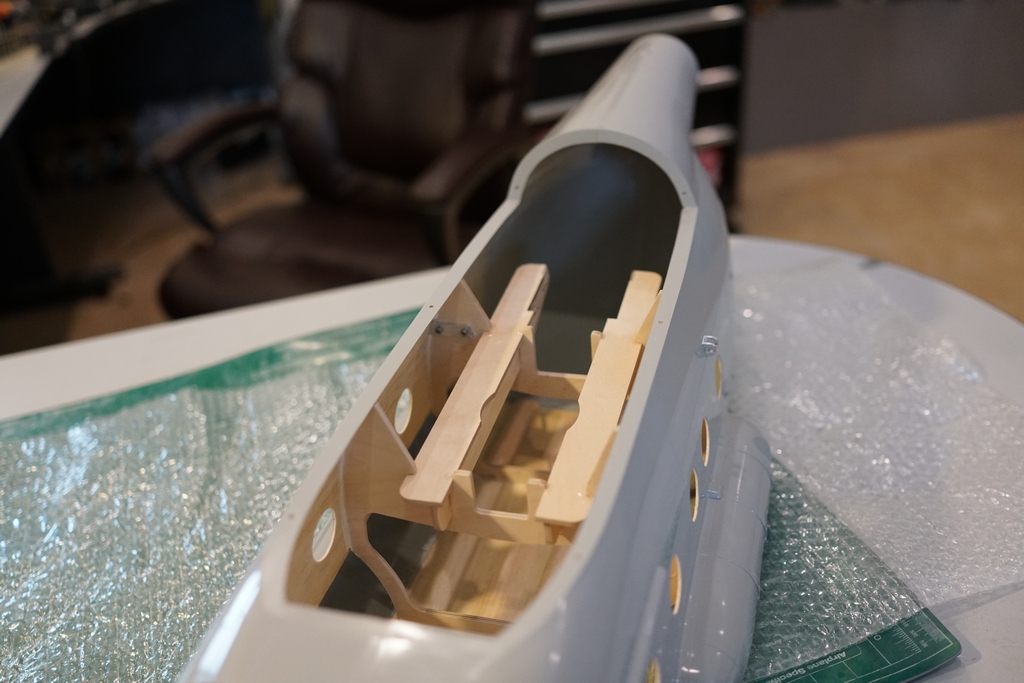
The other piece of woodwork is to mount the front landing gear to. It is pre drilled and the two almost cut out squares are for making the front gear steerable. Finish cutting them out and add a servo. The arms are already machined into the landing gear. So. last night, I got the epoxy and wood glue out and glued it all together. One thing it does say in the instructions was to glue the round windows in before gluing in the woodwork. I did not do this cos I am a rebel, and I could not figure out how to guarantee not to get paint on the windows when painting the model. I'll struggle after paint is done. The other thing I did not do is to epoxy the wood together. Wood glue is just as good as epoxy and sets faster. Wood glue, wood to wood. Epoxy, wood to fiberglass
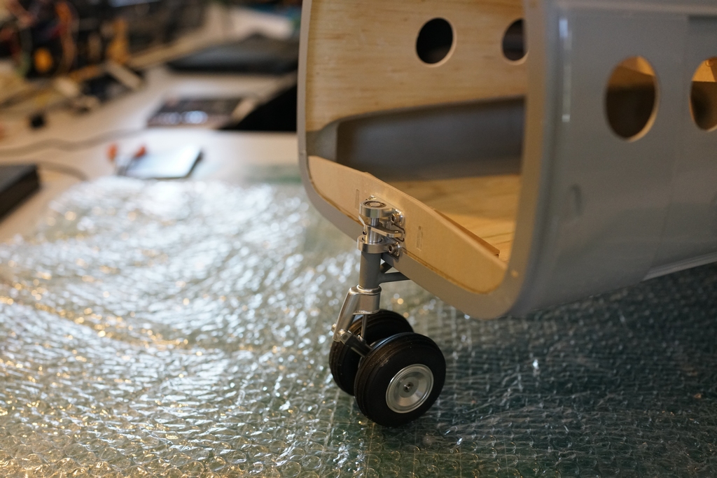
This morning I checked everything was set and then I had to mount the landing gear. I did the front first. 4 3mm cap heads through the pre drilled holes and then I had to drill 2mm holes though the V arms under the fuselage to brace it. 10 minutes work
Then I had to fit the rear landing gear. A single 3mm bolt goes through the top mouns, which is pre drilled and threaded. Then I had to drill 4 3mm holes through the bottom. The holes were already drilled through the fiberglass, I just had to open them out through the wood braces I had glued in last night.
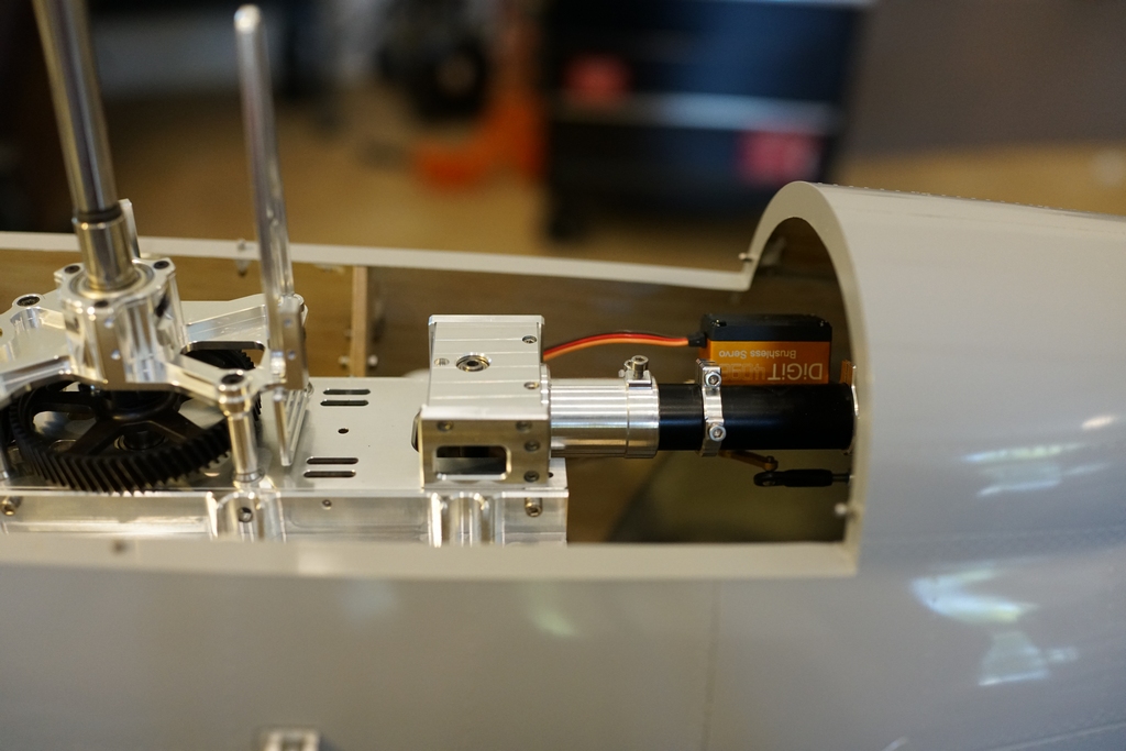
The mechanics I am going to use are from my long deceased EC145 which I dumb thumbed into the ground. There is no wear on the gears in the shaft drive conversion and when I set them into the woodwork, the shaft output sits exactly in the middle of the tail boom. Those mechanics flew 4 800mm blades quite happily so I have no worries about using them on 5 700 blades. Michaels mechanics use the wide belt conversion which I cannot do as my shaft drive conversion is too short. He has also prototyped a beautiful CNC side mount for his mechanics, while I will be using some pieces of angle aluminum. Michaels mechanics, intermediate gearbox and tail rotor gearbox are all in the design stage at the moment. he awaits some good weather to do some flying tests to prove their reliability before putting them on the market. I have dug deep in my junk box and found everything I need to get this bird in the air, but I have ordered a bigger motor as my little AXI that was in the 145 tended to run hot so I bought something with more power. So today, I get to strip the mechanics, replace anything worn and clean everything out ready to install the new motor and mount it in the fuselage.
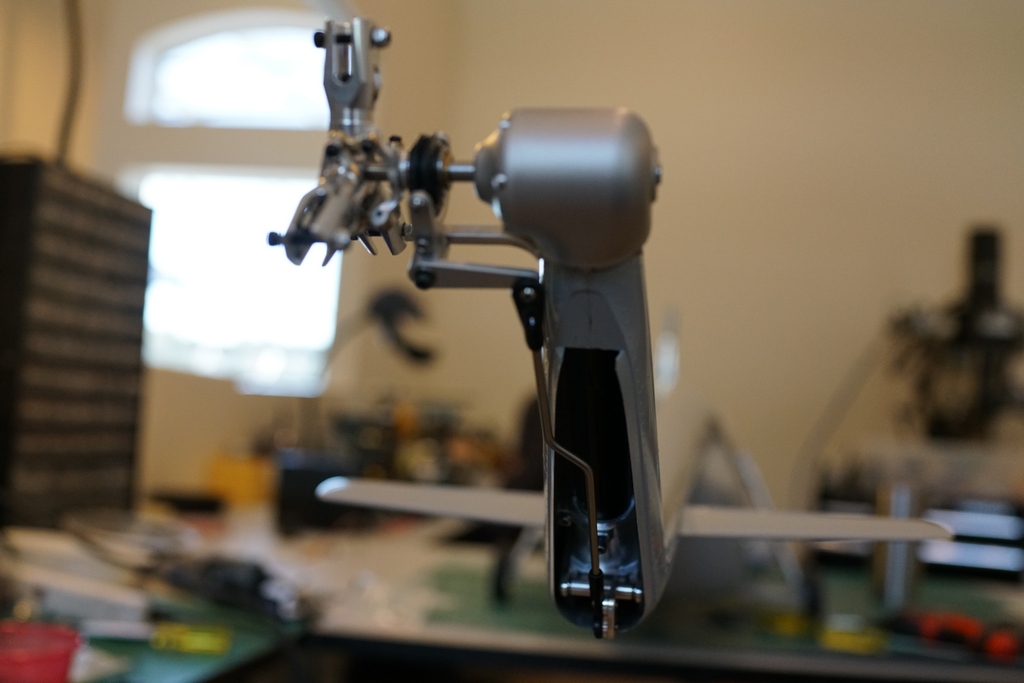
I asked Michael how much the mechanics were, and was very pleasantly surprised at the price. When I looked closely at them the whole arrangement was so simple, it would be much easier than using the old ones from the 145. I persuaded him to sell me a set even though they were not fully tested yet. After waiting for a while the mechanics arrived and then I had to go through them to see which Goblin parts were needed to complete the build. Eventually some of them arrived and I could get started on the assembly. First up was building the Goblin 3 blade hub and blade holders and fitting it to the custom gearbox
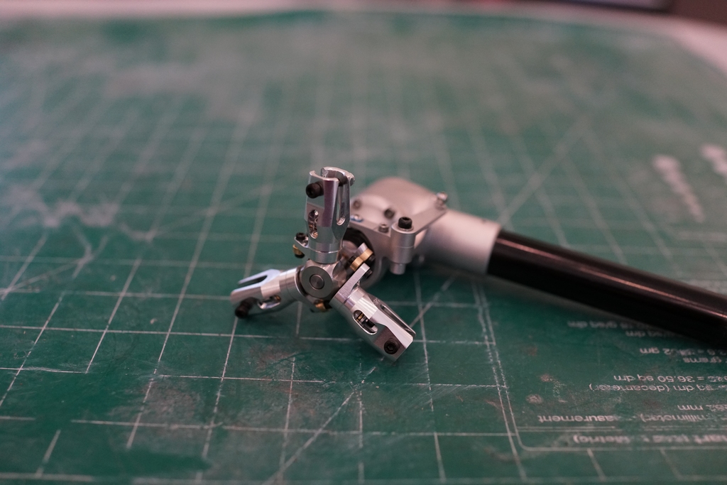
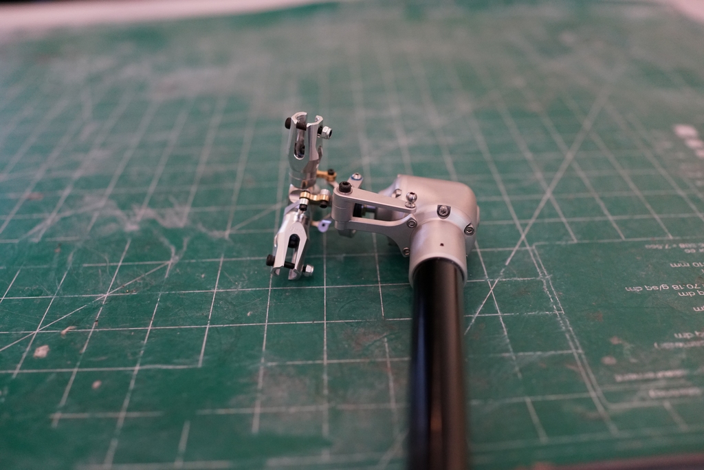
The gearbox was already pinned to the tail tube and the short drive shaft cut to size and fitted with Align couplers.
next I had to cut a 25mm hole in the top of the fin to take the gear box. That meant nearly cutting all of the top out, but there was about 1mm left
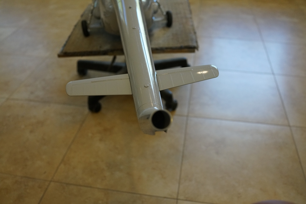
The scale gear box looks great snugged down, but it comes out for the next part.
Put it all to one side and pick up the tail tube with the drive shaft already installed. Slide the 45 degree gear box on and tighten up the clamp. Then I had to remove a screw, drill a 2.5mm hole through the tube through the screw hole and replace the screw. This locked the angle gear box in place. Then clip on the pre built pushrod.
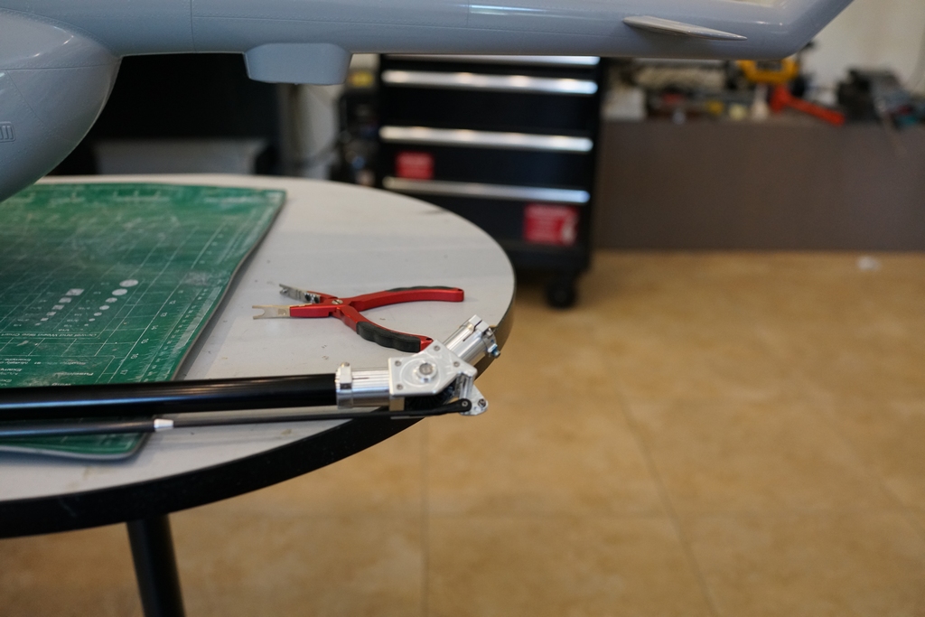
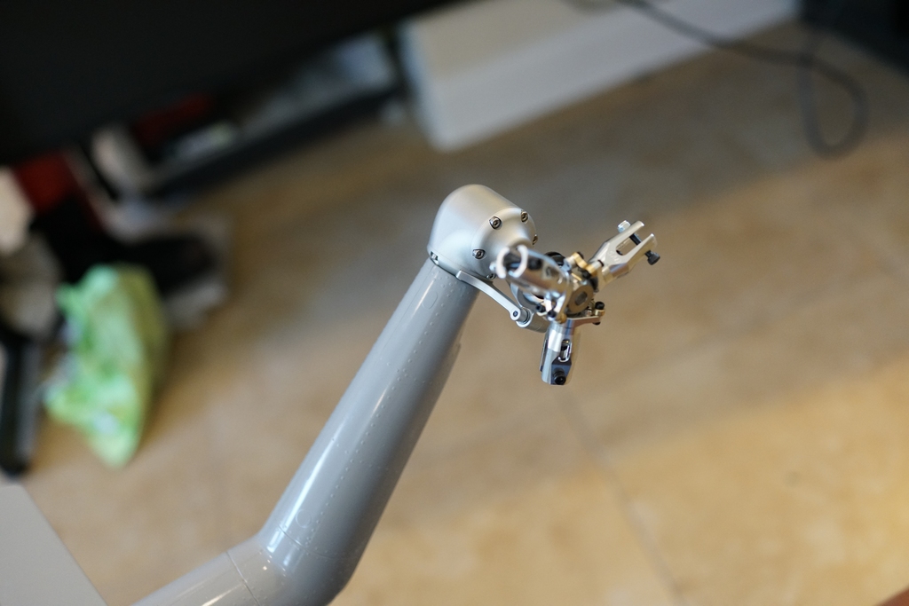
The next step was to fit the tail servo to the servo mounting brackets and slide them on the tail tube. Don't worry about the split servo lead, I'll explain that later
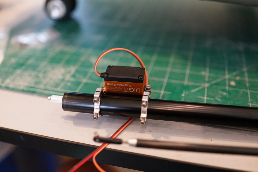
The pivot at the rear has to be in an exact place with the servo arm at right angles to the servo and then the clamps are tightened down. Then a 2.5 mm hole is drilled through the center screw hole. This locates the servo in the perfect position
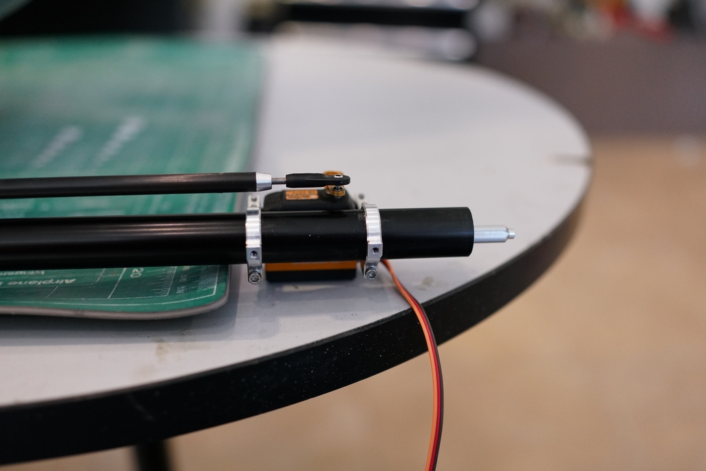
Now the servo comes off and the tail tube is slid into the tail boom with the push rod. The hole for the push rod needed a little sanding to allow the thick rod to go through. Its the bottom eye shaped hole.
Now the drive shaft can be inserted into the tail gear box and the gear box pushed into the tail boom Couple up the push rod and check it's free to move.
Now the servo can be slid on the tail tube and located over the hole I drilled, clamps tightened and a locking screw fitted
Now comes the really clever bit. The whole tail drive train is rigid but nothing is fixed down. The same clamp and locking screw arrangement is used on the mechanics, and they are bolted to the woodwork, or at least, they will be when I get the rest of the parts and I can finish the mechanics assembly. So now everything in the tail drive is rigid and wont move. I like it and it is that arrangement which made me discard the intermediate gear box and dog bone couplers which I was going to use
The next stage was very time consuming and expensive. I bought and set up all the electronics in one of the most comprehensive control systems I have ever put together.
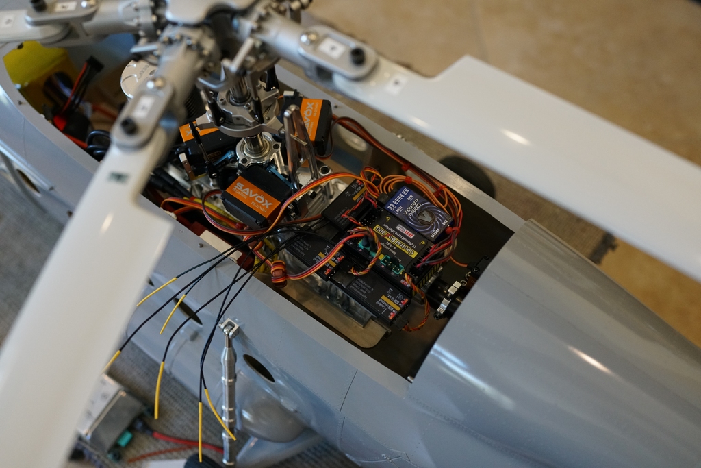
I think some explanation is required. I bought the servos, but at the top of the sales page it said be sure your power supply is up to par as these servos suck up the power and will cause glitches. So I invested in a CB200 power box for the Jeti. It came with a remote switch so I could turn the system on from the transmitter and 2 3 channel receivers. The idea of the system, once it is on, it that the receivers take the signal from the transmitter and feed it to the high power servo outputs. This was not what I needed, so one of the receivers was disconnected from the CB200 data input and connected to a servo output, just to provide it with power. Then a single wire UDI output went to the V-bar input. Another 2 core wire went there as well to provide separate power and ground, just in case. Now I had god outputs to the servos from the V-bar, but it was not going to be able to provide the necessary power. So, I split the signal wire from the servo and found another servo plug to put it into. That got plugged into the V-bar servo output. The power connector from the servo now went into the CB200, so now I have 40 amps of power capability from the CB200 available to the servos, and no load on the receiver or V-bar. I have to thank James at Esprit, Ron at Mikado and mainly Sandy Jaffe for their help in figuring most of this out.
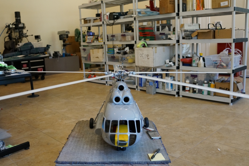
The blades finally arrived and got fitted. I had to press the 4mm ferrules out and fit the 5mm ones, and then do the tracking. Surprisingly 2 blades were 1 turn out, all the others spot on, so they all got numbered just in case.
Tomorrow I will finish the set up of the v-bar Neo and put my expo and pitch curves in, and then await the pleasure of helidirect, to supply me with a new set of batteries. My 6s 5000's have been purloined for use in Marcus's 407. Then I have to balance it and that will not be a small job. Meanwhile the 3D printer is thundering away making turbines for the inlets and generators for the APU. I must finish the design for the winch, but none of that will stop the first test hover. I wish those b@stards at Soloshot would get their fingers out and deliver what they promised months ago!
After a hard week painting and masking and more painting, final assembly can be started
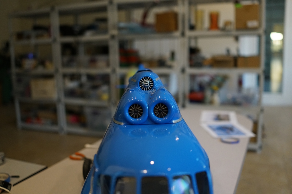
And then its straight back in the spray booth for a coat of gloss black where the turbine outlet is
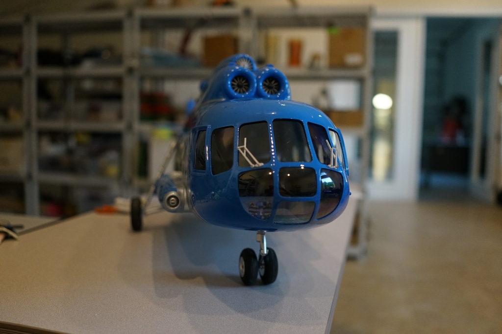
It will be back in the spray booth again later for an airbrushing of flat black for the exhaust. Meanwhile, the turbines and APU generator have been fitted
Wipers and auxiliary heater in the side pod are in
More airbrush work needed on the winch and exhausts and while that paint is drying, I will reassemble the mechanics
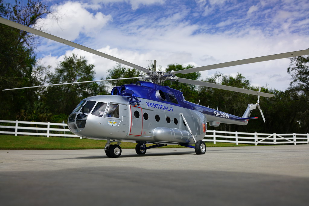
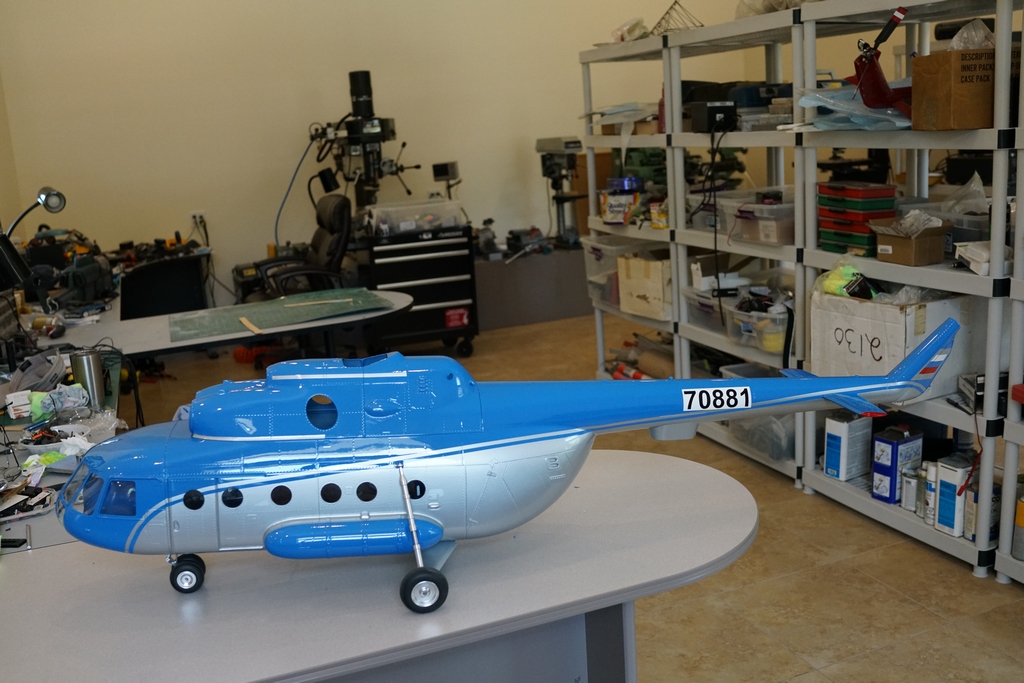
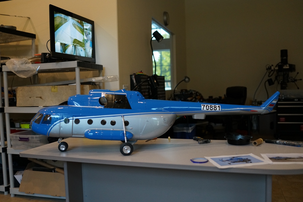
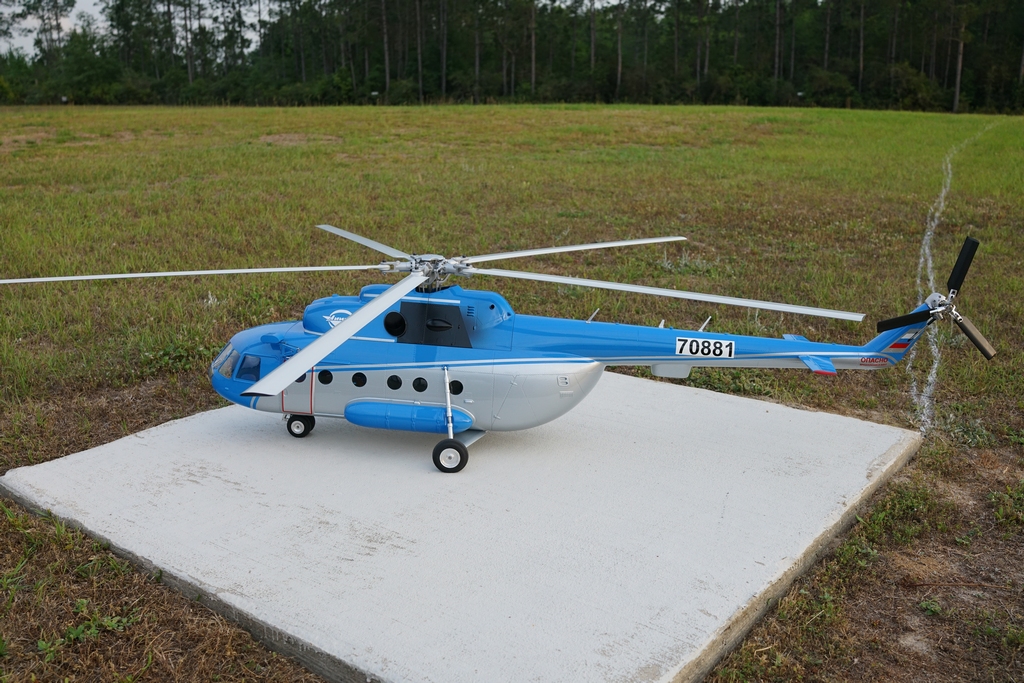
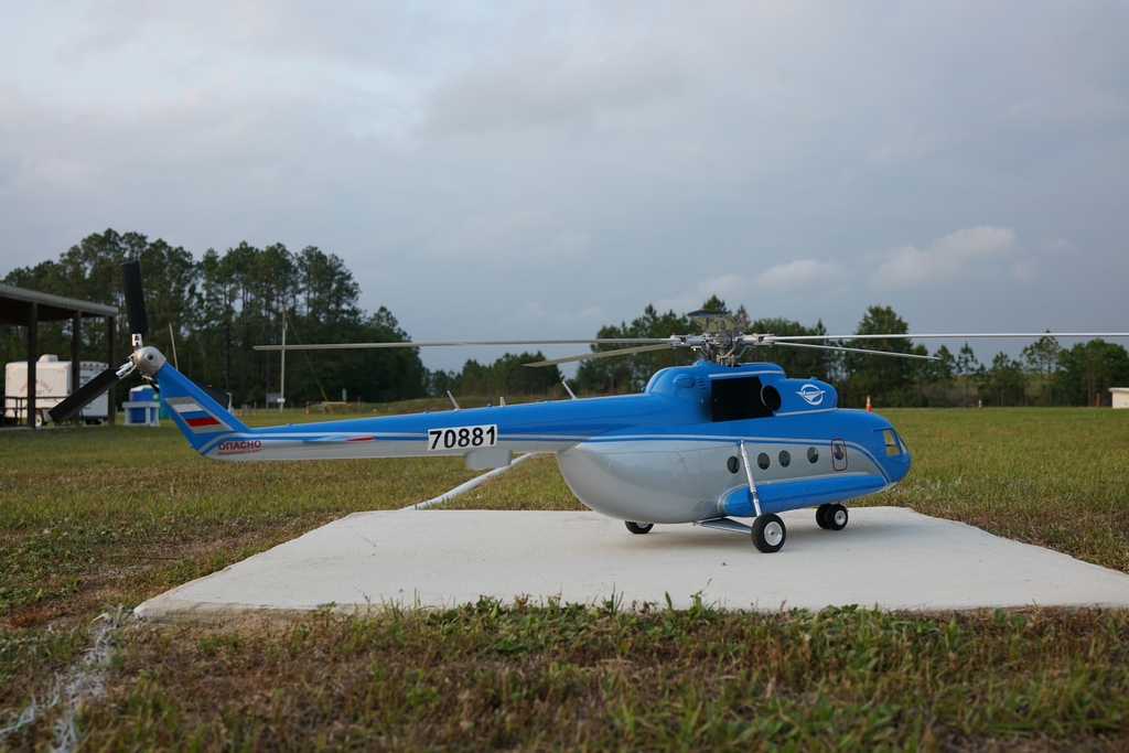
I have neglected to put some pictures of the finished model on here so here are some taken at Panama City fun fly.

A video of it in flight is at https://www.youtube.com/watch?v=SW4pTFyH-E8&t=18s
I liked it so much, I bought another one and tricked it out with retractable landing lights, beacons and strobes. A different paint job and it looks just as sweet as the first, which my Grandson has now stolen from me so there's 2 of them flying around in my back yard