Seaking Part 2
The base board for the mechanics needed a little trimming to make it easy to get in and out so while I was at it, I gave it a couple of coats of polyurethane. Then I set to work sorting out the rotor head.
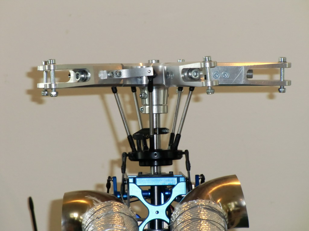
The first job was to take out the Vario swashplate and use one which had a bigger internal diameter to reduce the angle of the push rods as much as possible. I had to fit the ball links onto the ends of the pitch control arms as I wanted to put them on the inside again, to keep the angle as near vertical as possible.
I wanted to use some nice plastic ball links I had from Germany which were easy moving but the ball was very difficult to get out. That gives me more confidence that the links aren't going to come off. So, I ended up with an OF swash plate and driver and I took the balls out of it and replaced them with some specially machined pan head screws holding the German links in place. The links needed the flash sanded off the bottom to clear the base of the swash as the screws are angled down and as the center of the ball is now lower than the hole, my measurement was off by a thou or two. Nothing my trusty dremel couldn't cure.
Then I grabbed some 4mm stainless rod, cut it to length and turned the ends down to 3mm for threading. With a lot of fiddling I managed to get all of the pitches on the blade holders within 0.2 degrees and have none of the threads showing. I hope the tracking is right first time as it will be a nightmare to adjust the tracking. I have machined up some extra screws for the swashplate just in case, and I have figured out a way to get the old ones out if I strip one of the sockets which are now very shallow. This is the final result. At mid stick I have 5 degrees of pitch.
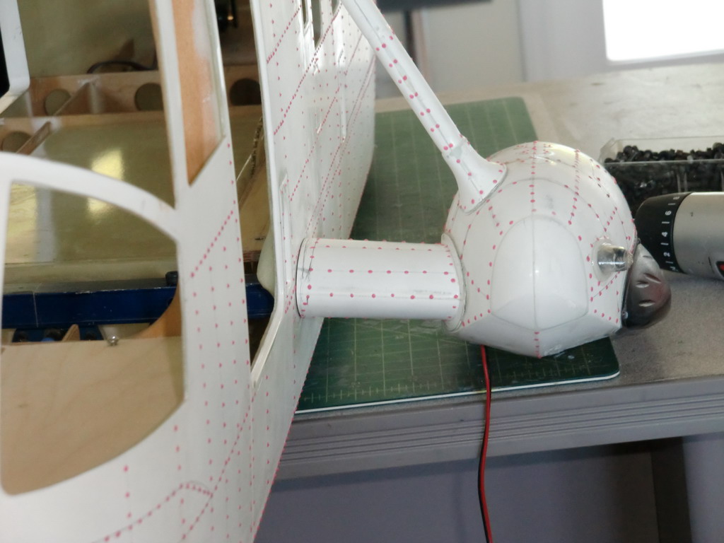
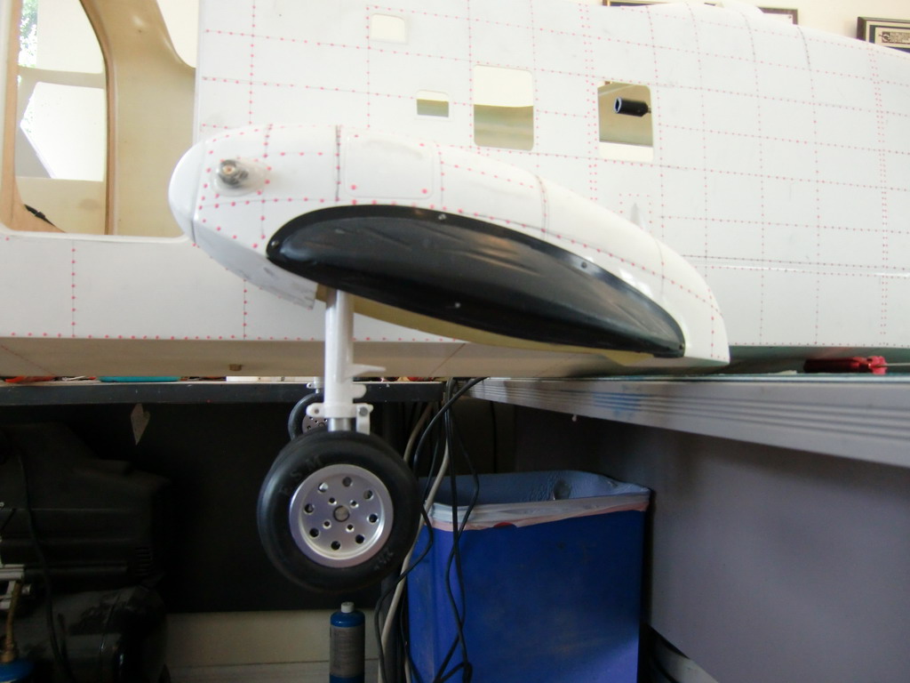
Time to turn my attention to the landing gear. Once again I have some parts which look good, but simply dont work, or are badly fitted. The sponsons and thus the position of the landing gear, is bolted to a 15mm square aluminum tube through the center of the helicopter. As the holes in the aluminum tube have been drilled in the wrong place, if I don't fix it in position and I put the fuselage on it's side, then it can be allowed to slide down. The top sponson meets the fuse like this, but this is after sanding it to fit.
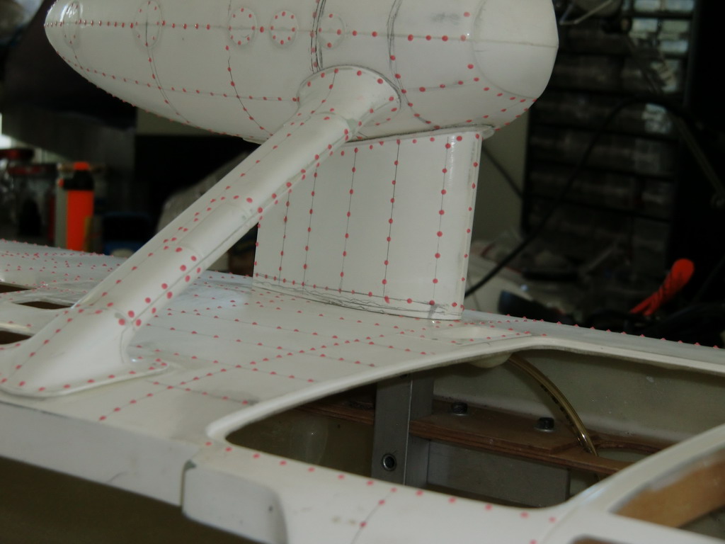
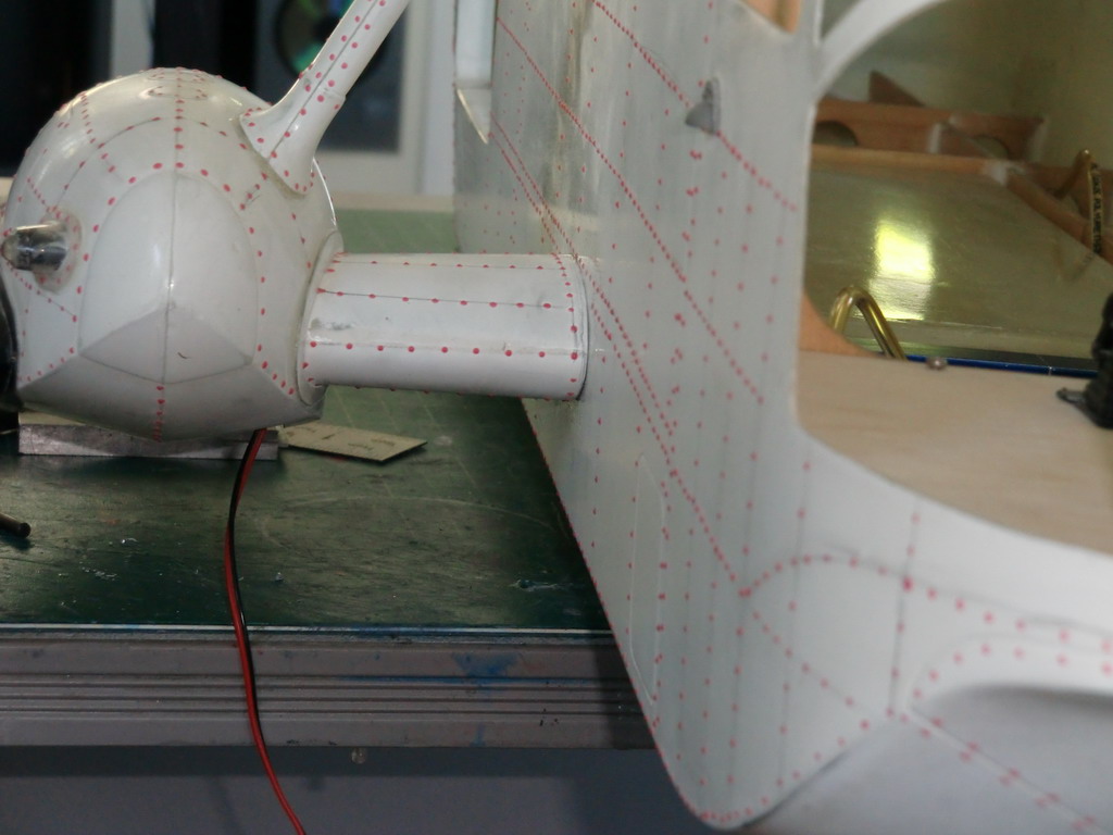
That is a good fit now, but the other end looks like this.
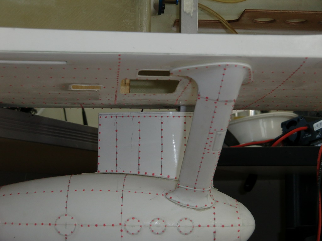
Now if we look at the holes in the tube which mount it to the plates in the fuse, they are out of alignment. There is one other problem. The holes in the tube are 5mm and the holes in the plates are 6mm, so you need to get a nut on the bottom to tighten them down. Now if you imagine having the turbines exhaust over the top and trying to mount those bolts through the turbine mounting board, you can see it just isn't going to work.
 So the first thing to do was to switch the two support brackets around and then redrill the holes and tap them out to 4mm. Then comes the tricky bit. I turned the tube through 90 degrees so I got a fresh start, and then drilled new mounting holes. Now the tube is centered in the fuselage. Then I measured the gap to the sponsons accurately and redrilled and tapped the holes in the tube to mount the sponsons. I did make the mistake of measuring one set of holes and assumed that the other set would be the same. Silly me! However, a bit of attention with a needle file had everything sorted out. After a days work, this is how it ended up.
And the other side looks like this
I decided it would be easier to get the retracts working with them outside of the fuselage. This somewhat out of focus photo shows a lot of the elements involved so even though it is a mess, I'll leave it like it is. The 6mm rod goes from one side to the other and the landing gear is fixed to it with set screws. The actuating mechanism is very ingenious, if only it had been properly made
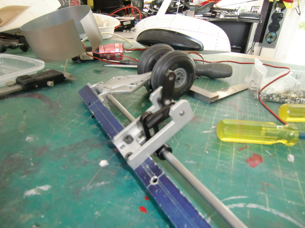
The black piece mounted on the rod has a slot milled in it. The horizontal piece has a pin in it which slides in the slot, or it would do if the slot had been milled properly, but the mill had been left too long at one end and so there was a ridge which the pin got stuck in. The top black metal piece is the actuating arm which is connected to the servo. The way it works is that the pin slides down the slot to the bottom, moving the gear through 45 degrees. Then it slides back to the top, which is now horizontal. Consequently at each end of the travel, the slotted piece is trying to push directly at the pin piece at right angles to it. This stops it moving without any load being put on the servo. So I decided I would use one of my old S5050 servos which is a wing servo for a giant airplane! I needed the weight up front and these servos had never been used so any valid reason to use them was good.
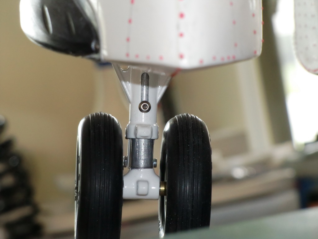
To solve the problem of the rough surface inside the slot was solved by cutting and shaping a small piece of stainless steel shim and gluing it in place at the bottom of the slot. The other problem was those plastic wheels! An order to Troybuiltmodels.com soon had a set of metal rimmed rubber tired wheels on the doorstep. The problem was the holes through the center were drilled with an inch drill sized just a little too big for a 5mm rod. So, it was off to the scrap metal box to find some tubing of the right size.
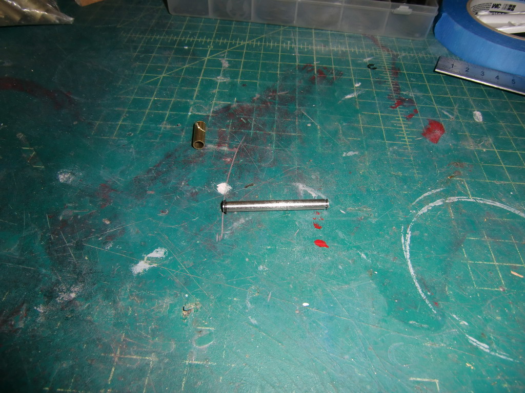
I made up an axle out of one of those self destructing Vario 5mm flybars and cut some 0.7mm grooves in the ends for circlips. Then I drilled the center hole out to 1/4" which was a tight fit on the brass tube
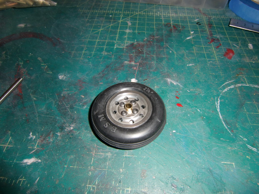
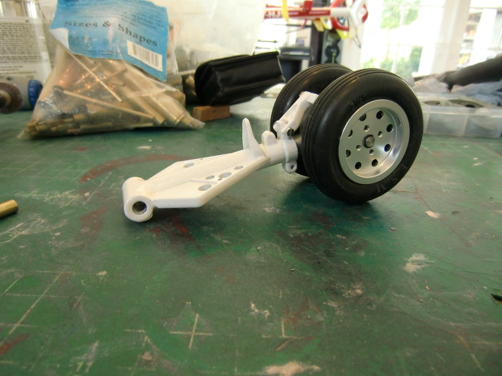
Precision fitting the brass tube with a big hammer and a block of wood had new bearings and a spacer in one fitted to the wheel. I powder coated the landing gear white and this is the final assembly.
Well, there was one more thing to do. The sliding shaft for the axle mount needed sanding so it could slide in the main body. Then I added springs to give some suspension. Then another problem reared its head which explained why the shaft had been left rough and jammed inside the tube. Once it was freed off, every time the helicopter took off the shaft dropped to its lowest position and the two anti rotation links were the only things stopping the wheels falling off. They went straight in line and then the wheels were locked in the down position and the suspension didn't work again!
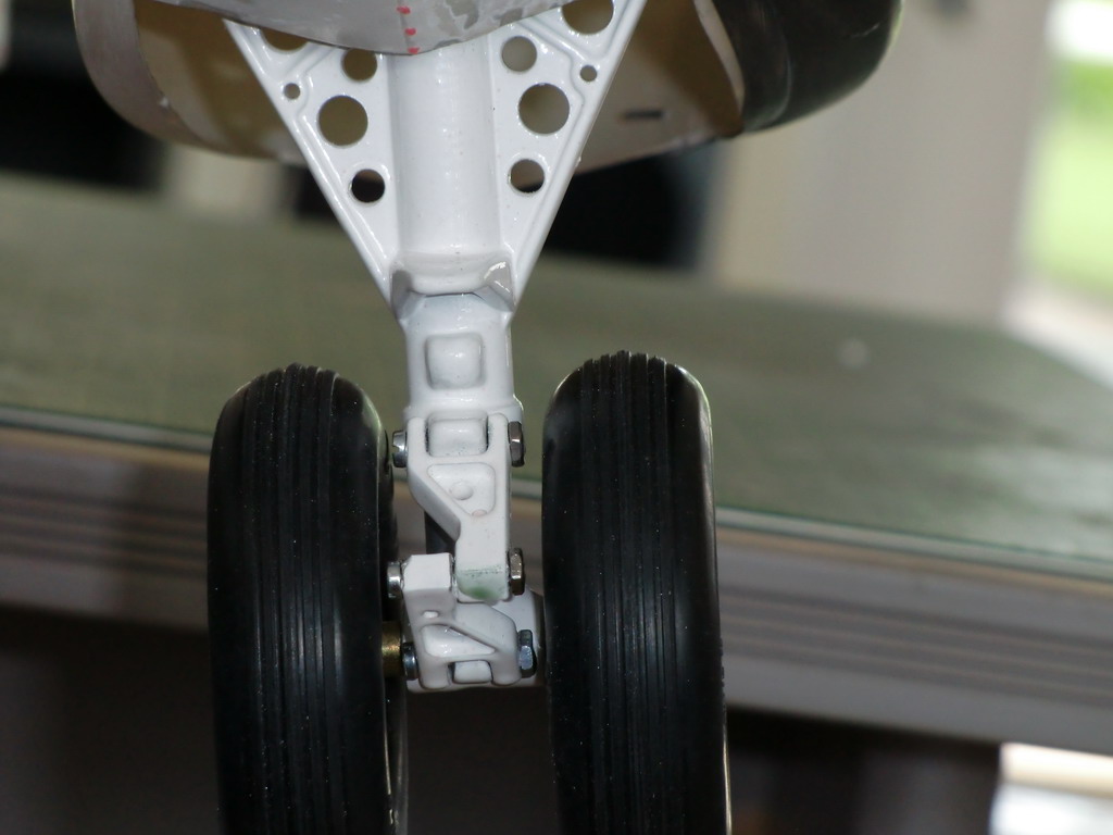
I had a chat with Joe Howard and he set me straight. The best way to do it was to mill a slot and then drill a hole and thread it so I could put a bolt in there. Then I could cut the head off the bolt leaving it flush with the slot and no one would be able to see it. When I milled the hole I found the strut case thickness was less than 1mm so I elected to leave the bolt head on to stop it going inside the strut and jamming everything up. While I was checking things with my full size picture file, I noticed I had assembled the wheel assembly the wrong way round and the scissors should be pointing to the front. That'll teach me to assume Zander knows what he is doing and everything is as it should be, but In should know that by now. I took the opportunity to reverse everything and noticed that there were flats on both sides of the rod to locate everything so they knew it had been wrong once, and did it the same again.
So here's the wheel assembly as it is now
And the slot at the back with the screw head
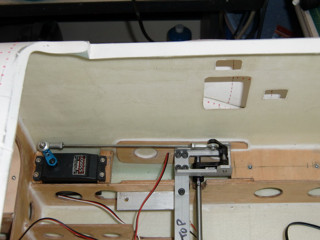
and the servo linkage from the giant S5050 servo.
I made a video of it working to show the system in operation. Its here http://www.youtube.com/watch?v=XcTrr8qGeIs
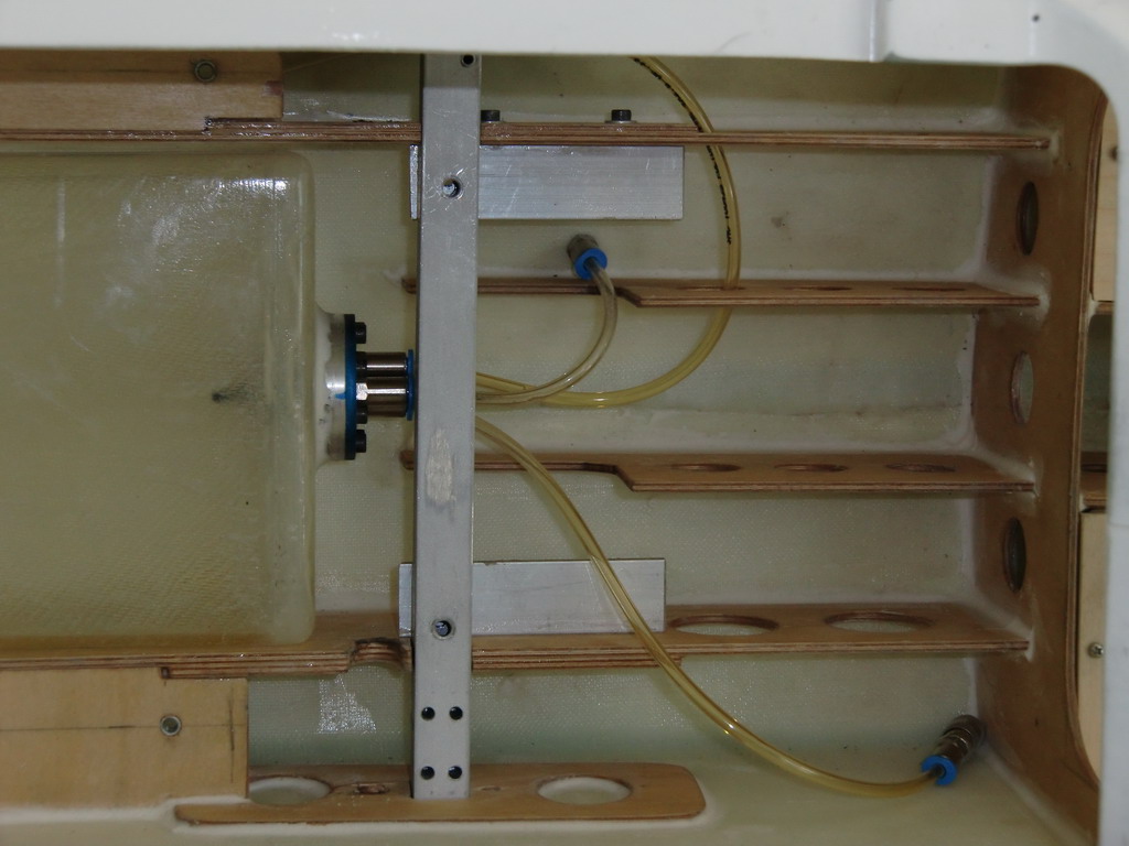
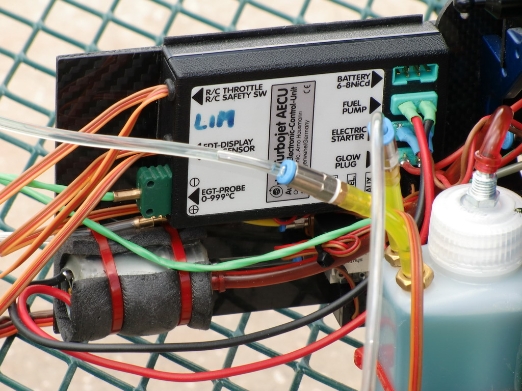
This is a job I have been putting off. I could not figure out how I could fix all the pipes and valves in place and not have to disconnect them every time I removed the mechanics from the fuselage. Then I hit on the idea of mounting a piece of Carbon Fiber vertically and fixing everything to that
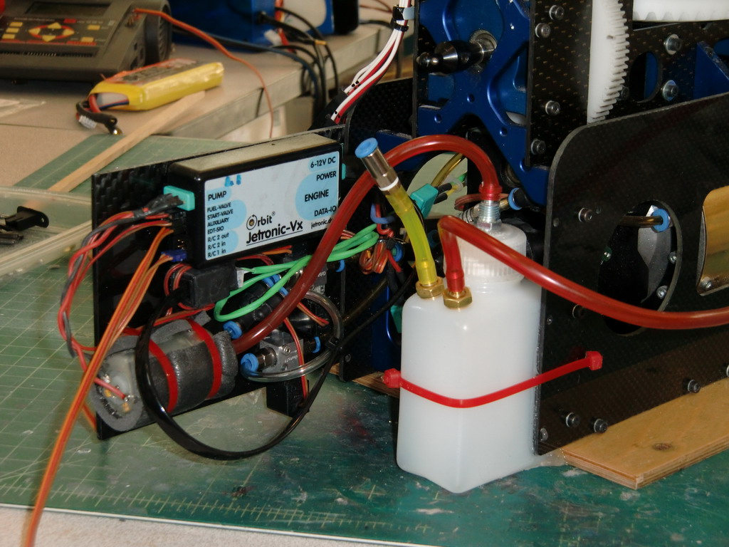
It turned out pretty neat and all of the cable and fuel pipe runs are very short. Then I cut a piece of ply and fitted it into the fuselage behind the turbine to mount the Rx and Gyro box on. As I wanted to be able to get to the two connectors for the A123 battery packs, I decided to run them down this side and have the electronics panel only secured in place by magnets. A couple of coats of polyeurethane to protect the wood from kerosene and I am ready to mount the electonics
It's been a couple of weeks since I updated this buildup, mainly because I haven't been building, I have been sorting problems. I installed the AR 9100 receiver and tidied up the wiring and after trying things out 2 or 3 times, the receiver stopped working. It gave an output which was the failsafe setting, and thats all, it wouldn't change even though it was properly bound to the Tx. I bought another one and it did the same thing. It worked for while and then stopped. So I fitted an AR9200 and that has functioned properly ever since. Of course, it is different from the AR9100 so I had to cut a new wood panel and relacquer it. I had sent the first 9100 to Horizon and I decided to call them and ask them to check it carefully. They said they would and meanwhile suggested I try a new set of satellites. So I switched out a set from an AR12000. No difference. So I put the "faulty" satellites on the 12000 and switched on, and bingo, both Rx's started to work. Horizon sent my first 9100 back saying there was no fault but a satellite had to be plugged into socket A and none was. As I just jammed them in any sockets and sent it off, it didn't surprise me and I will be very careful about using the 9100's in future.
Then I fitted the mechanics in the heli ready for an initial spool up with no blades to be sure everything was ok. There is no way to bleed the fuel through to the kerostart system so I gave it several tries pumping a little through each time. Finally it fired but gave up before it could spool up to full speed. I tried again and the battery was flat. I fitted a new battery and the starter would not spin the turbine. When I took it apart it was fried. I managed to find a new starter motor. They are very common and very much in demand by the glider guys for powered glider flights so finding one was not easy. When I fitted it, I found the ECU was also fried. Whether the ECU fried the motor or the motor fried the ECU I dont know.
After digging around on the internet for hours I managed to find the cell phone number for Mr Pahl, gave him a call and found he didn't speak English, so I sent him an e-mail which he is ignoring. So I decided to pull the old ECU off my Jako turbine with kerostart and use that. A little reconfiguring and it should have been fine. Once again, I could get the first fire, but then it died. After 4 or 5 goes I gave up. I pulled out another Jako ECU and reconfigured that one to work with the Pahl, but as gas start not kerosene. I pulled the kerosene injector, which looked as if it had seen better days, and fitted a glow plug.
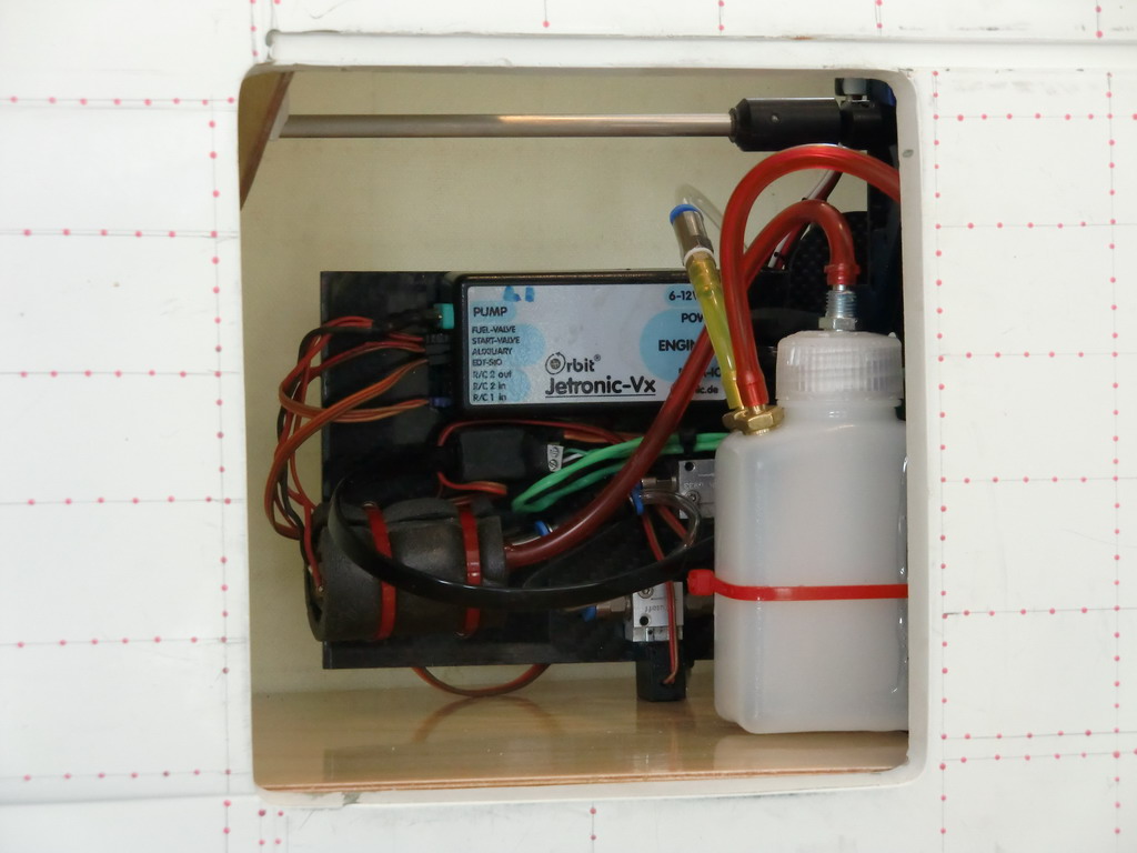
Then the excitement started. I filled up the gas can with propane and left it horizontal on my trolley. Hooked up everything else and hit the go button. The turbine spooled up and then there was an enormous bang as liquid propane was injected into the turbine. The valve closed and then the rest of the gas burned off in 4 foot flames out either side. Then the valve opened again and there was another explosion which blew out the flames and the thing spooled up as it should. I was 100 yards away and traveling fast at this time. I put the gas cylinder vertical and tried 4 or 5 more starts and was very happy that it started each time with no fuss or explosions. This is what it looks like now, as I had to change the mountings as the ECU was twice as big as the old one.
I'll tidy it up a bit more when I fit it in the fuse and hook it up to the Rx. Next is the wiring for the lights. I just need to tidy this up a bit
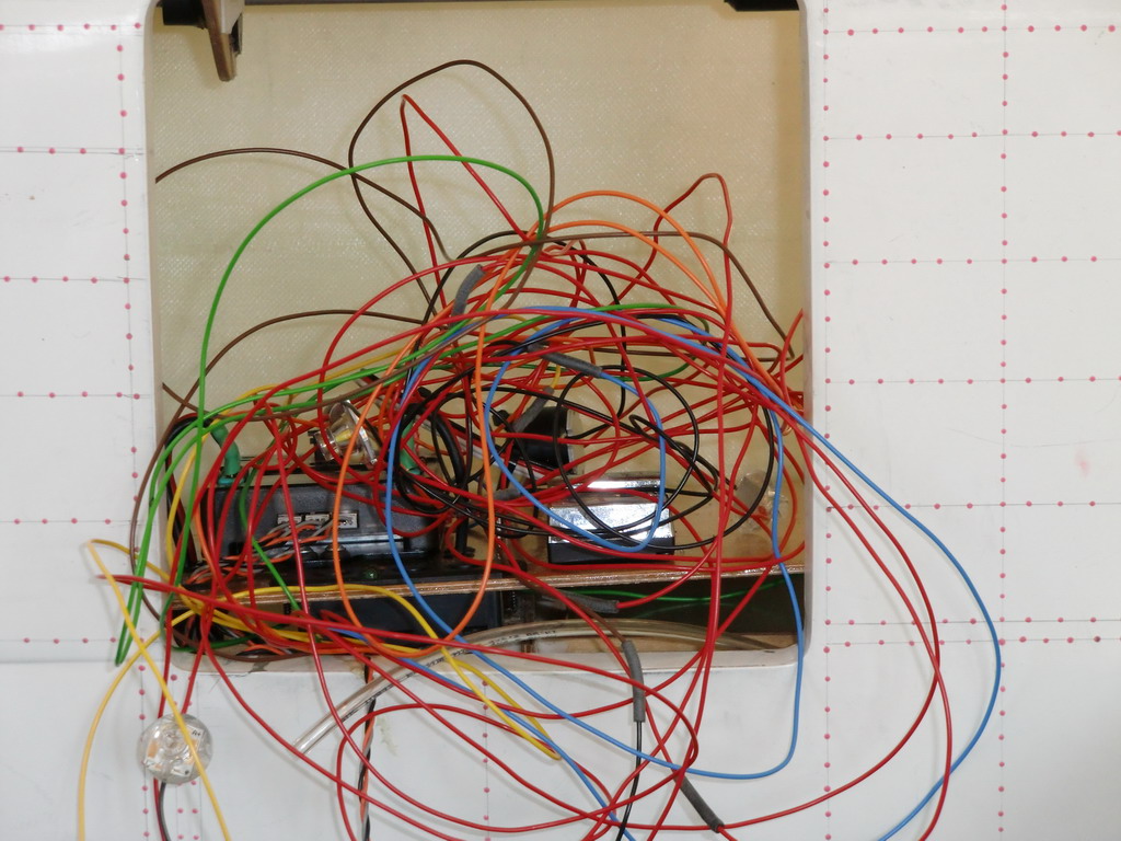
I have used one of East Coast Scale helicopters driver boards with a development amplifier to allow the use of Luxeon Leds. I have some very interesting optics to go with these and my next update should have a video showing how well they work
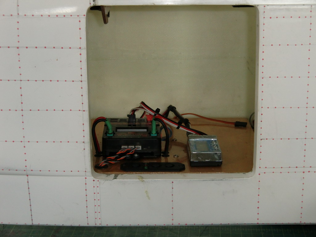
This is the receiver and gyro panel now with the lighting controller underneath and all the wires loomed up and out of the way.
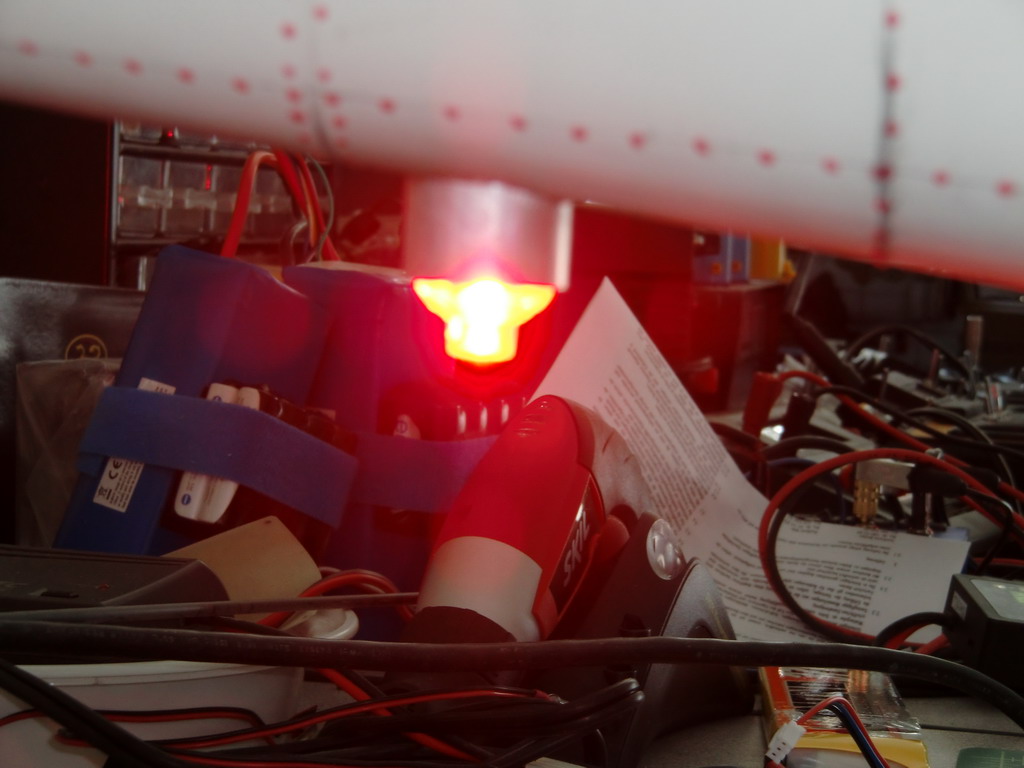
I managed to get one of the strobes flashing just as I clicked the camera shutter. Note the brightness and the fact that you are looking at it from the side. It is this bright through 360 degrees due to these new optics I have found. I'll do a video of them working outside in the sunlight tomorrow to show how bright they really are in bright daylight
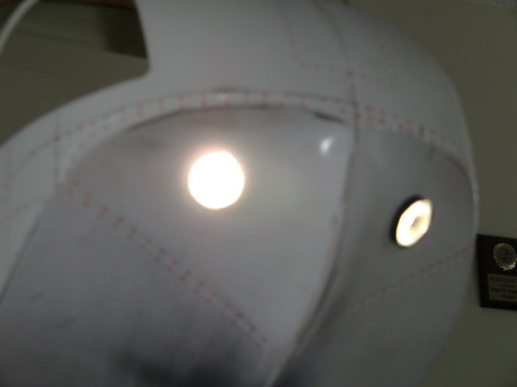
The lenses are just pushed into place or held there with tape so they aren't perfectly aligned yet. Here is the front landing light with a lens over it to spread the light. My poor little camera got a bit overwhelmed by the brightness of the light
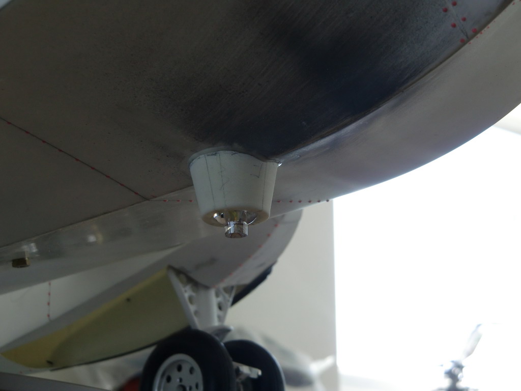
This is the bottom rotating beacon which is white. I have left it switched off so you can see the shape of the lens which projects the light at 360 degrees around. The mount is something which I whipped up on my 3D printer. It took about 20 minutes to design that cone and an antenna mount and a couple of hours to print them, while I was outside in the pool.
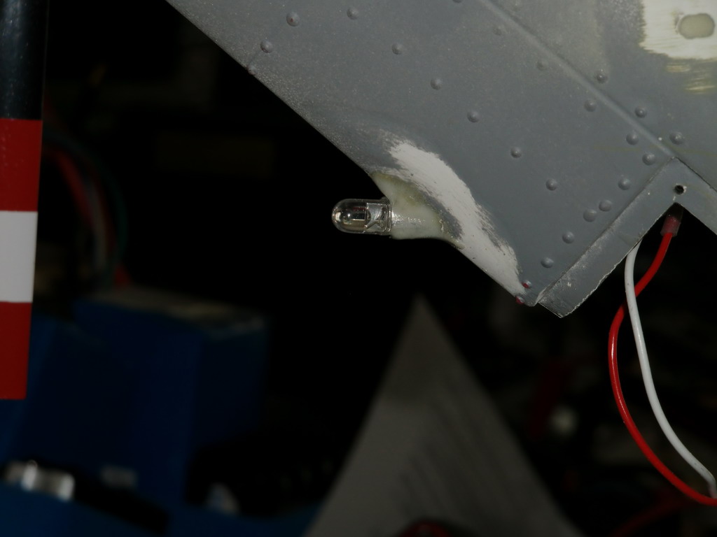
The last light is not really a light at all, it is the indicator for the turbine status. I got a piece of 1/4" aluminum tube and glued it into the fin and the trimmed the LED down to fit. After painting it will be fixed in position so that the LED just protrudes slightly
A very poor video is at
http://www.youtube.com/watch?v=YdviWhC_ytE
It will show you the lights in full sunlight and the fact that the shutter and the data rate on the beacon are similar and in sunlight it has a weird effect. Indoors, it looks just fine and in both situations it looks fine to the eye. Strange!