After an enforced break and a voluntary one I am back in the saddle. The enforced one came after I had some problems with the turbine and when I called Mr Pahl he told me it was 6 years old and needed updating. Good old Lars, he strikes again. I just ordered an new one. Then we had the fun break at IRCHA. A bit toasty but a blast as usual. Then a few days waiting and the new rotor head came in from M-Copter and the blades came in from M-Blades and the turbine from Pahl. It was like Christmas, oh and I had a birthday in the middle of it all so it was a good time. That's now over and I got down to work.
The first job was to see if the I could pull the old turbine and just fit the new one. That was instantly obviously not going to happen as the new one had a much larger intermediate gear which would make the turbine sit very differently. Taking a lot of measurements, I found that the two sets of mechanics were very similar, but that intermediate gear drove the tail drive and that was fixed. Thus the new mechanics had to be lowered.
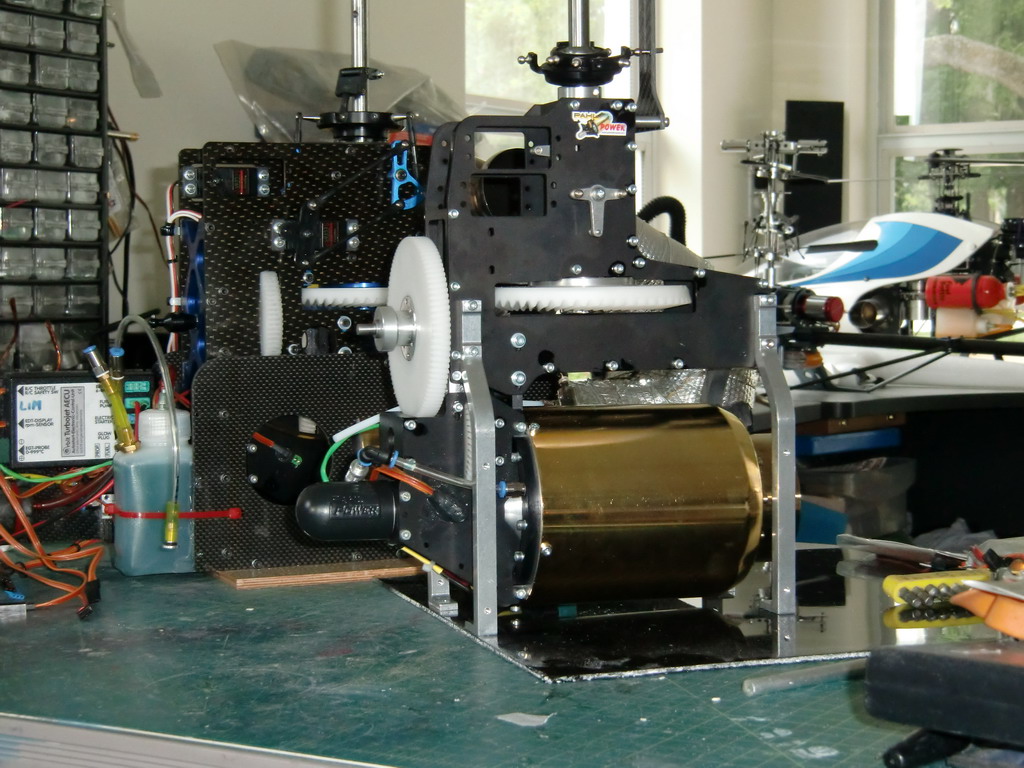
The old set was mounted on a piece of plywood 6.5 mm thick. I needed to lower the new set by 5mm so I thought that if I replaced the wood with a 3mm thick piece of CF and machined 2mm off the bottom of the mounting legs, I would be in line, so it was off to the mill. This is how it turned out. Tomorrow I get to have fun sawing up pieces of CF and milling them to shape.
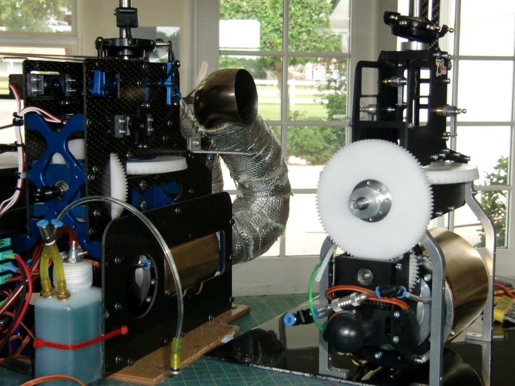
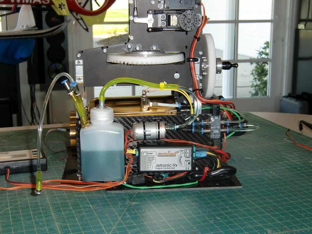
I assembled the turbine on a nice piece of CF and the tail drive lined up perfectly. A small adjustment on the length of the drive shaft had everything shipshape and I was ready to assemble the ECU,header and plumbing. This is how it turned out.
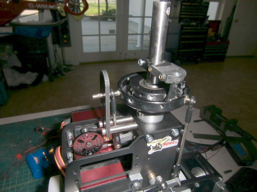
Next, the anti rotation bracket for the swashplate was way too big, and was mounted in the front. I cut it down and made up a couple of steel spacers. Then I drilled and tapped the top bearing holder and mounted the bracket securely. As you can see in the picture below, I have used an OF swashplate as it is nice and big and I want the push rods to be as near vertical as possible
Then came time to fire it up and this is the reason for the large gap between posts. The ECU would read the RC but not get past the mid point when it came to trying to fire the turbine with the Tx. Sometimes it would not even read the RC. I contacted Pahl and they shipped me out a new one which arrived while I was at the Dalton fun fly. I plugged it in and this one would not even learn the RC. To contact Gerhard Pahl, it is necessary to e-mail his daughter Stefanie and she translates your English into German and gives it to Gerhard. I told her of the problem and received no reply. I knew Gerhard would be preparing for Jetpower which is this weekend and Stefanie probably could not reach him or she was too busy. Then I called Orbit in Germany and spoke to a nice guy in their technical department who went through everything with me. We found 2 problems which is why I was struggling. The first ECU was faulty, and the lead which connects the ECU to the receiver as also faulty. When I fitted the second ECU and a new cable, everything sprang into life. A quick spool up showed the turbine and mechanics were smooth and ran well and I was good to go. So thanks to the technician at Orbit!
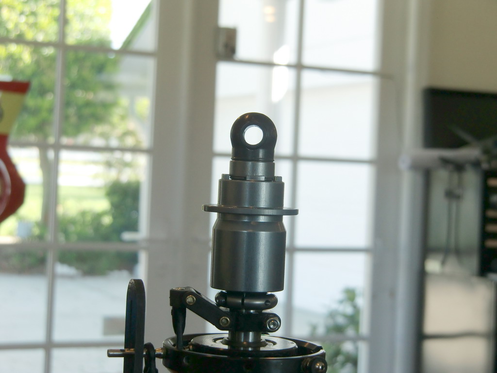
The next part of the assembly is so very different, I will detail it step by step. The first step was to open the head mounting hole in the mast to 5mm and cut the mast down to have the distance between the top of the mast and the center of the hole at 5.2mm! All will become clear in a minute. The rotor head is built up on the mast and the first step is to fit the base and the rubber dampeners. I selected the soft ones.
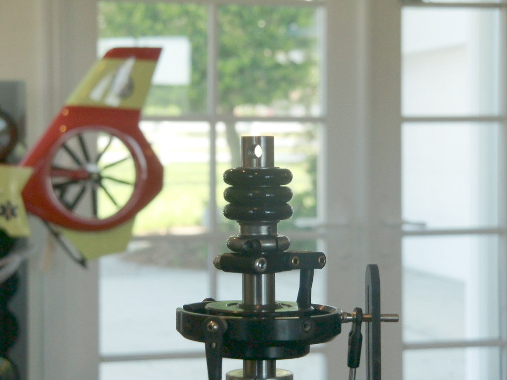
Then the outer cover is slid over the O-Rings
The cover can wobble within the constraints of the O rings
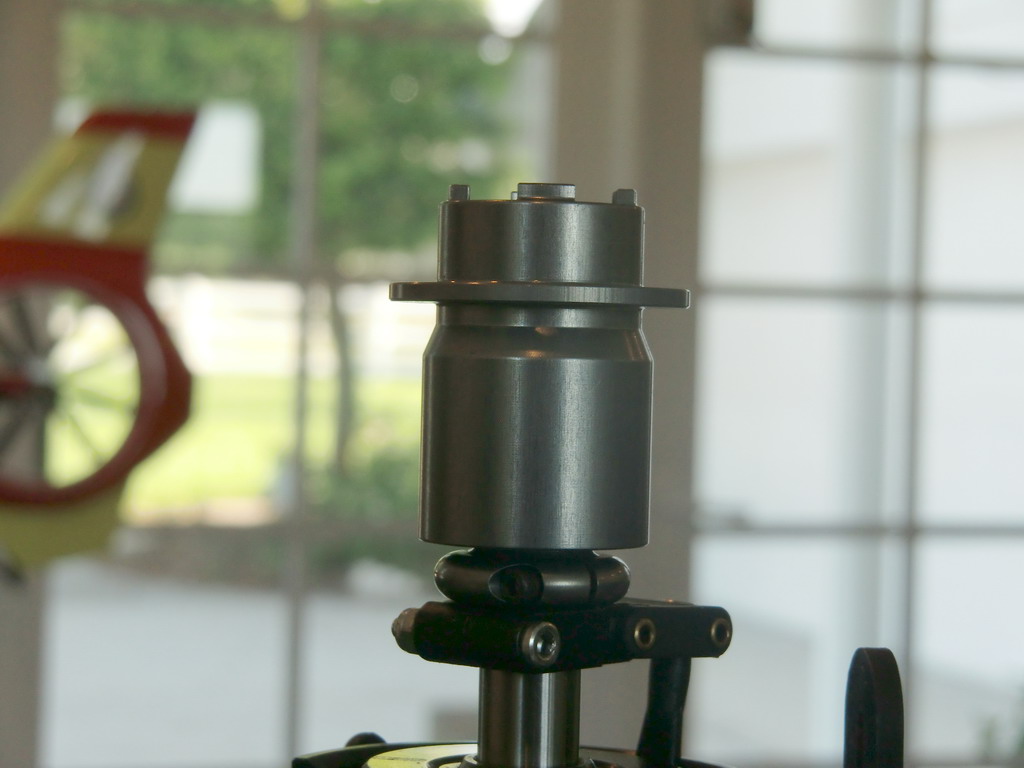
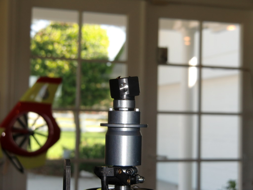
The the Cardan bearing is fitted, and you can see the hole in the mast nearly lined up with the hole in the bearing. The bearing center is milled so the top of the mast is touching the top of the hole inside the bearing.
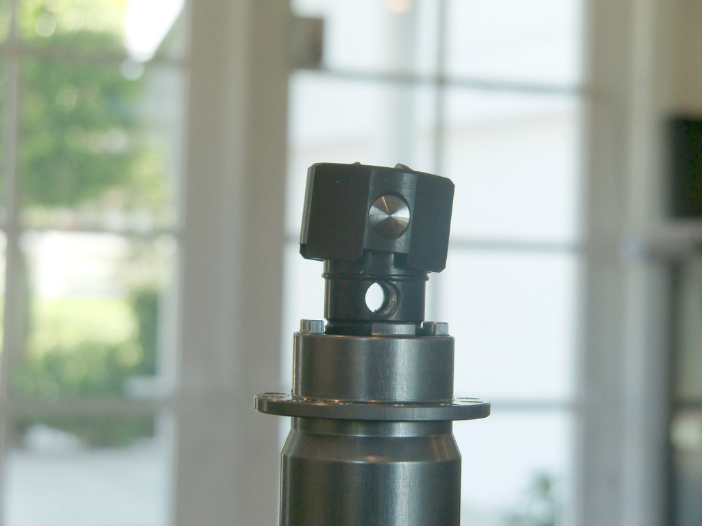
The Cardan bearing is like a universal joint with limited movement and while continuing the assembly, I removed the pin and outer section of the bearing assembly. Then I fitted the 5mm pin through the bearing and mast to lock it into place. A sleeve is slid over the pin to stop it coming out and a circlip is fitted under the sleeve to stop that from moving. None of this fitted easily, all the tolerances were so tight I had to press everything in place and I hope this part never has to come off.
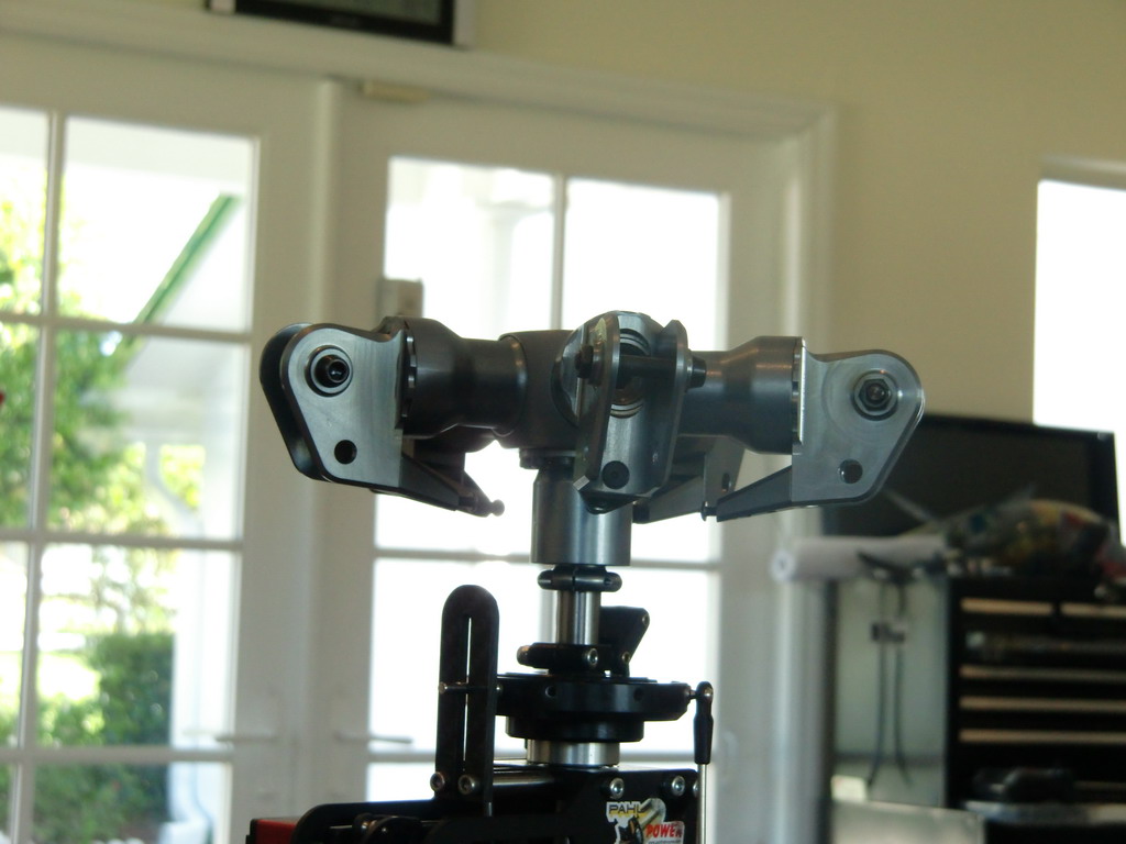
Then the Cardan bearing is reassembled and the pin replaced. Another sleeve fits over it to stop it from coming out.
Then the rotor head is fitted with a lot of 2.5mm screws and the clamps tightened up on the O-ring inner.
Finally a set of push rods were made up and fitted. I had enormous travel due to the size of the swashplate so the pitch curve is very shallow and the cyclic settings are around 30%
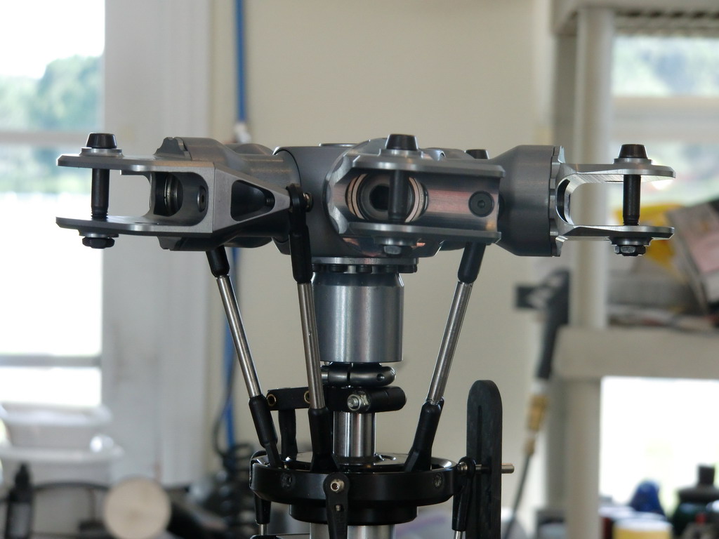
It is very unusual to have the dampening on the entire rotor head rather than the individual blades and it will be interesting to see how this head flies.
This morning I got it kind of assembled and most of the loose bits tidied up out of the way so I spooled it up to full power with no main blades on
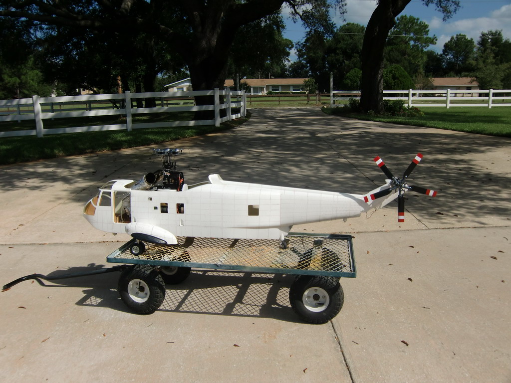
It was a bit of a non event really. It just spooled up and made a heck of a noise and spun up happily. So, it was time to bite the bullet, fit the exhaust properly and remove all the bits which could get tangled up in flight like lights etc and then fit the blades on and go for a test flight
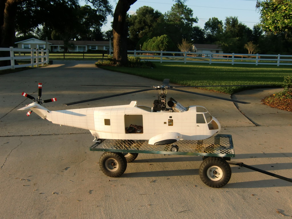
I took it into my pasture and fired it up, and it died on me. I tried several more times and then tried a new battery with no success. So I brought it back into the driveway and charged up the battery. I tried again with the same result. Then I tried again, and it took. It soon spooled up and was at an easy idle so I wheeled it out into the pasture and set her down in the grass carefully trying not to cook any of my essentials as the turbine was still running. I started to spool it up, and then remembered I had not set the phasing. A quick twiddle of the knob on the MC-24 and I had 45 degrees in and then I spooled her up again, almost in the dark. The strobes on the back were blinding and very distracting. However, it spooled up nicely, tracking spot on with no adjustments needed. Thank you M-Blades. I fed in some pitch and she lifted up and with a few clicks of left aileron sat there as smooth as silk. Quite remarkable. I'll try and figure out this starting problem tomorrow and then make a video of it if I can.
Once I hooked up the GSU the problem became obvious. The UAT was restricting the fuel flow and so the turbine could not accelerate up to idle speed in the allotted timespan. The cure? Remove the UAT and then it started everytime. This is a link to the first test hovers.
http://www.youtube.com/watch?v=suybgwwN2s0
Now it's time to start fitting it out and prepping for paint.
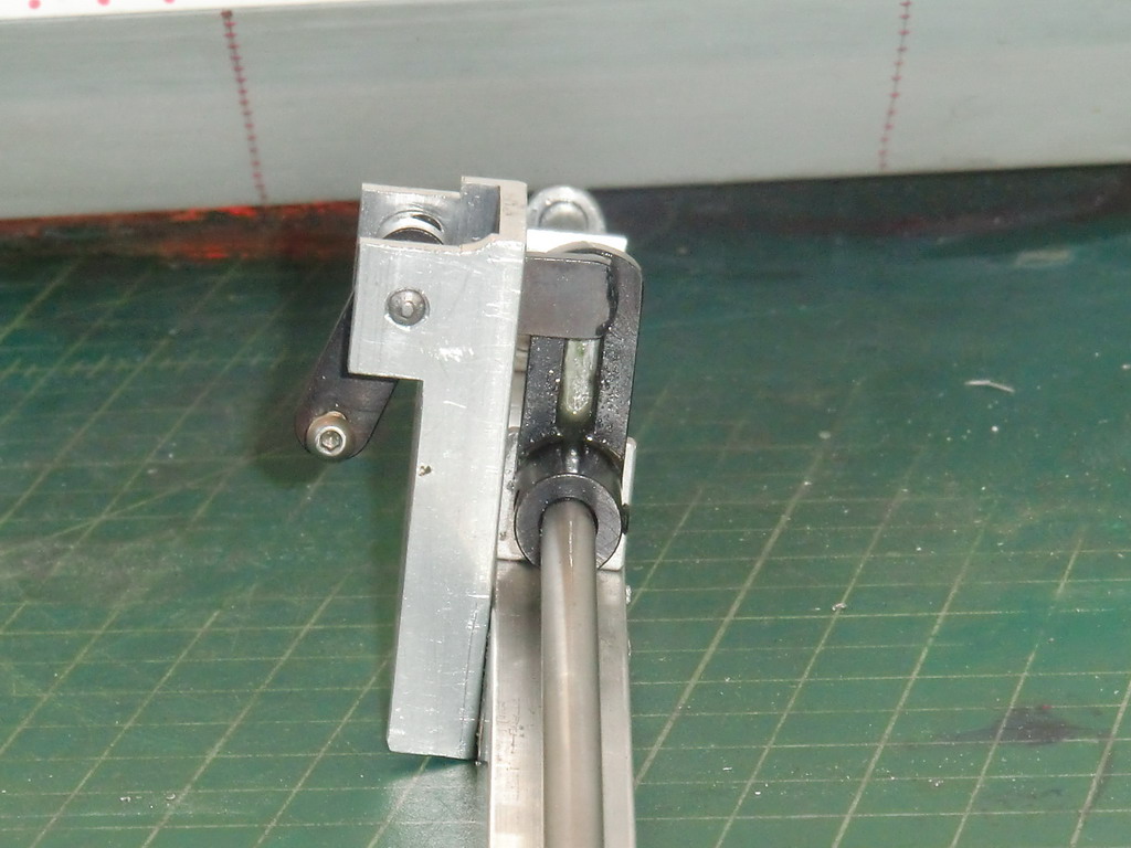
A friend of mine who also has one of these models warned me his landing gear collapsed several times. I had mine collapse while I was test flying it and I decided to remake the control system for the retracts. I got a new piece of aluminum tubing and remade all the screw holes, but first, I machined a block of aluminum, cut it into sections and glued it inside the tube at the point where strength was needed.
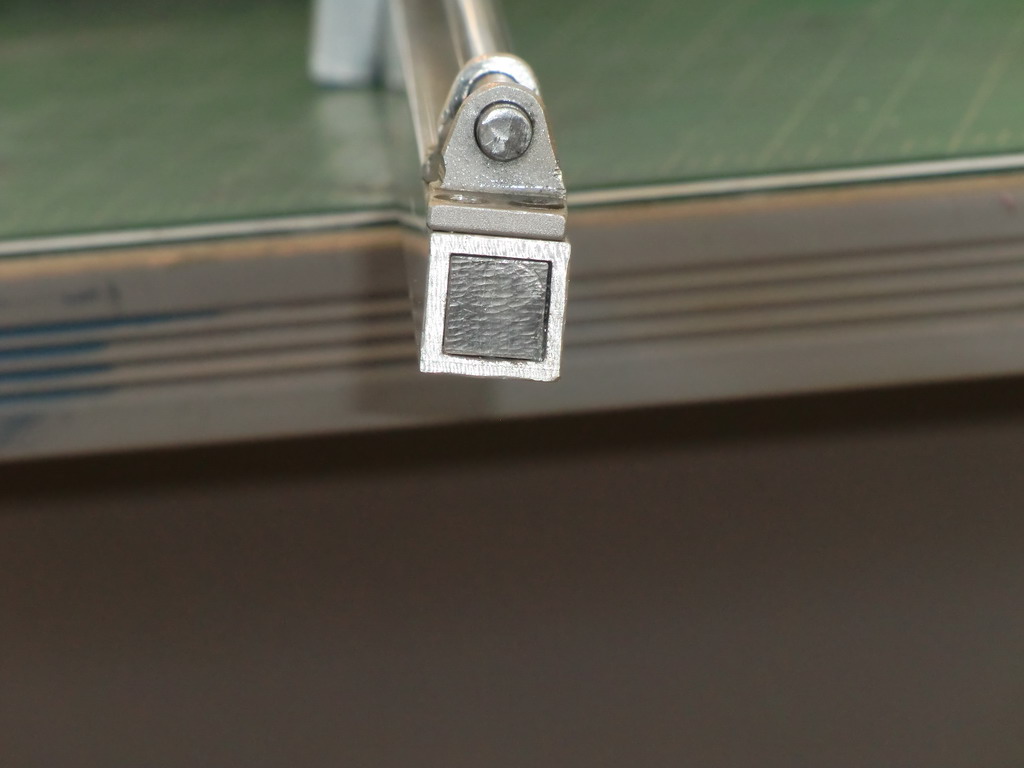
Although desirable, it is not essential that the landing gear rotates through 90 degrees. What is essential is that the levers are at 90 degrees to each other so that the servo is not under any load when the gear is up or down. With a few adjustments on a new mount and a bit of judicious grinding on some ends, I managed to get the travel I wanted
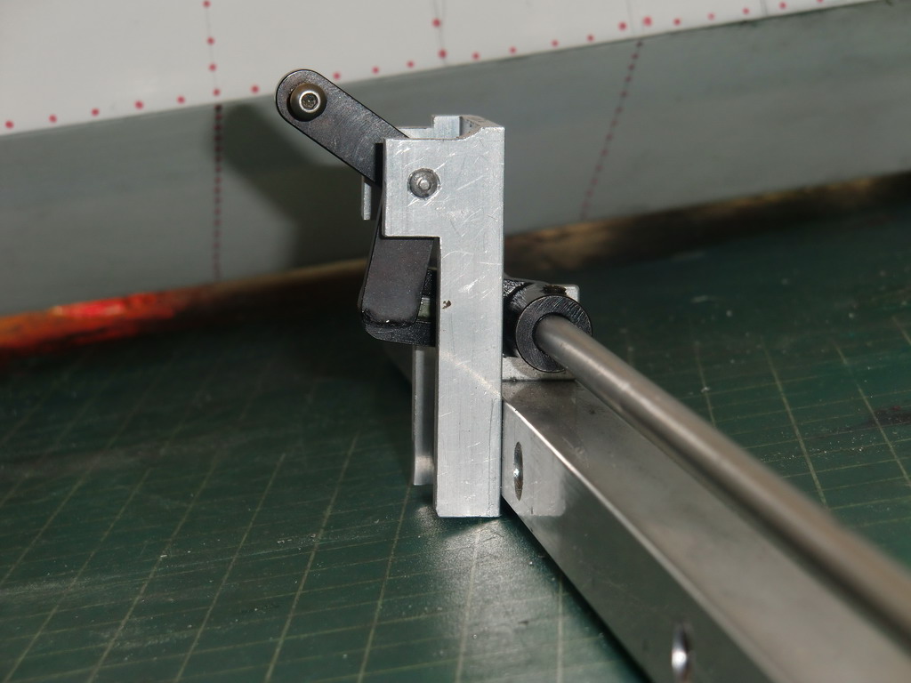
The piece with the slot in it is now at 90 degrees to the piece with the pin it it. The piece with the pin had its back to the camera, but you can tell which one it is. Job done.
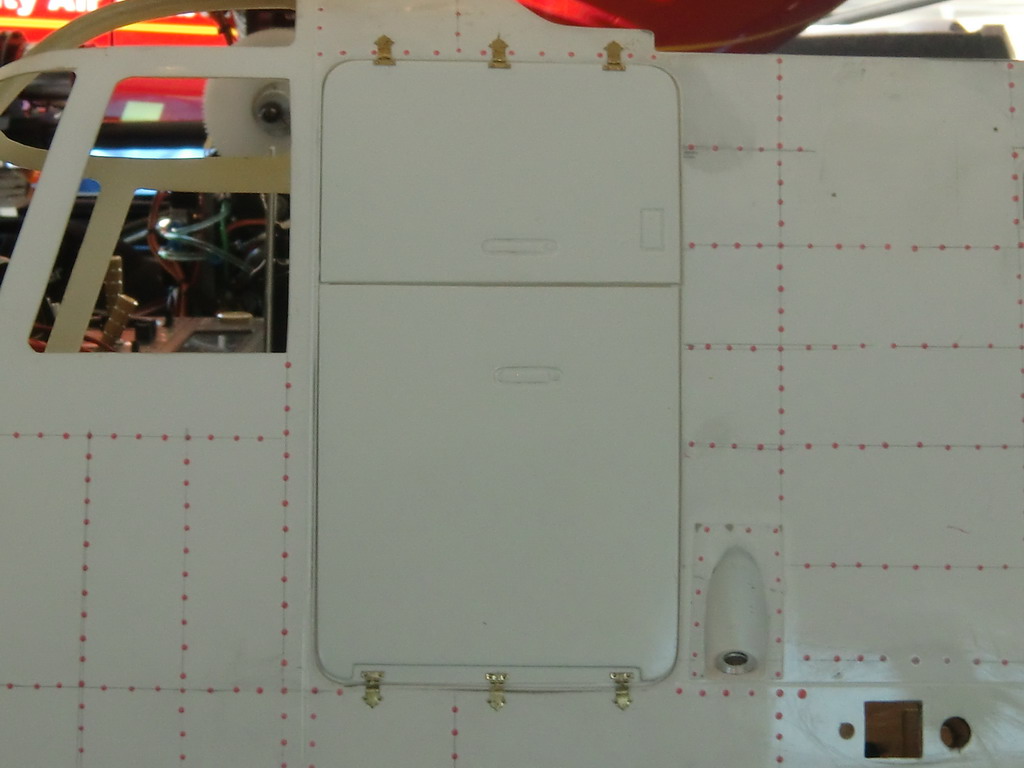
2 more major jobs to do, the doors. I mounted the smaller door with some tiny doll house hinges and then cut it in half as per the full size.
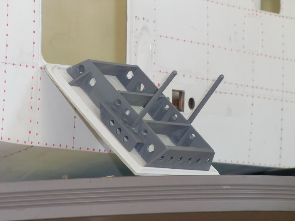
At last I got to make something on my 3D printer which was for me! It was as much of a learning exercise as anything and took me a long time to do, but it was satisfying. I am referring to the steps inside the door. This is how they turned out.
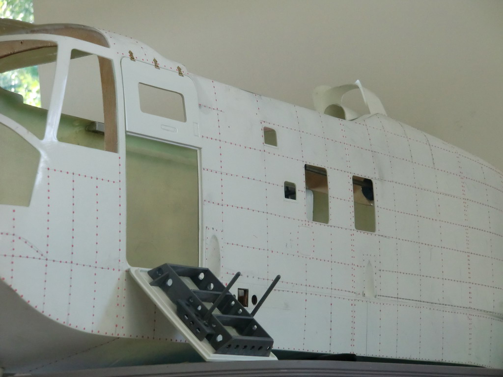
A closer look shows all the different angles which was the part which posed the challenge. I muddled through it.