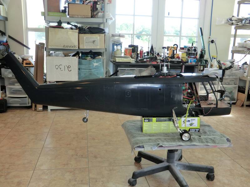
Seaprite Part 2
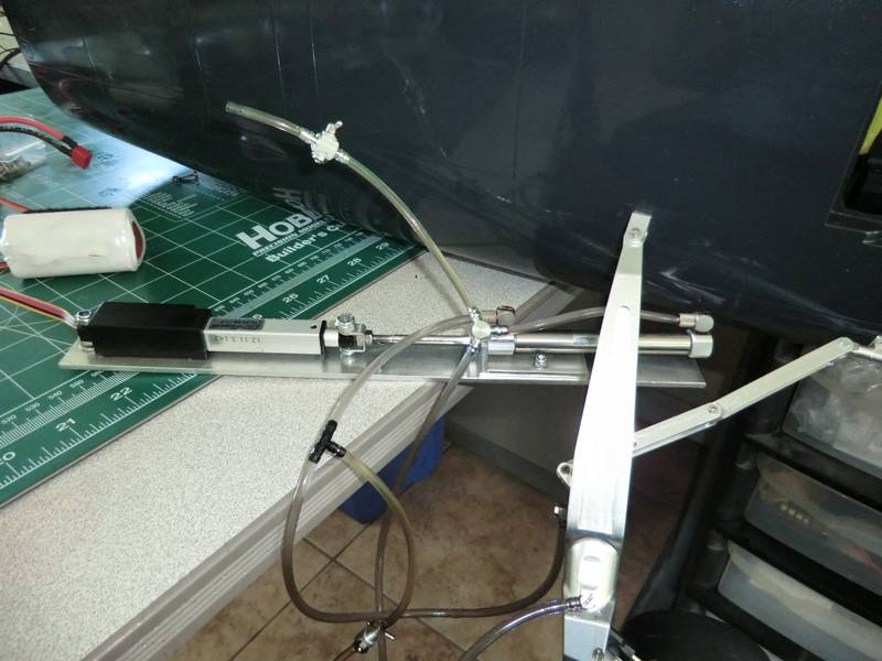
For the last several days I have been trying to make the retractable landing gear work in t same way that Gavin's worked. No matter what I did I could not get the gear to rise into the stowed position in the same way that his did. He put a video online which showed it getting stowed with a satisfying clunk. Mine stopped about a inch short! The first thing that I did was to fit a T piece in the hydraulic line with a shutoff valve connected to the T. With the aid of a syringe and a small oil bath I managed to be able to remove all of the air from both lines. I thought this would solve the problem but I was wrong!
after spending nearly a week messing with this, getting covered in oil, and getting very frustrated I decided that maybe there was another option. So I looked up the manufacturer's website of the control board. This is a very versatile piece of electronics which allows an RC input to control the linear actuator. This pushes the RAM and hence the hydraulic oil goes to the cylinder and moves the cylinder piston. I had been running this from another receiver with the whole assembly laid out on the bench for easy access. I used the same A123 battery pack that I intend to use in the model. Further reading showed that I could actually run the whole system up to 24 V but the maximum voltage recommended for an external inputs was 12 V and a suitable connector was supplied. What I had been thinking during my attempts to make this work was that if I used 12 V to supply it I would need to supply a RC signal of 12 V peak to peak. Carefully reading the manufacturer's manual, it said the RC input could be applied to the same connector. However you could not connect both the 6 V and the 12 V at the same time. So I cut the power supply line from the RX and fitted an external 11.1 V lion battery and tried that. That solved the problem! Wheels went into the bay with a satisfying clunk, and came down perfectly just over ensure that when they were down they stay down. This whole system has been very carefully thought out by the manufacturer in that the linear actuator locks up after a couple of seconds of being in its final position. This keeps the pressure in the hydraulic system the same, and the mechanical system that Gavin has designed ensures that not only is it hydraulically locked into position it is mechanically locked into position, so if any air gets into the hydraulics landing gear will not collapse.
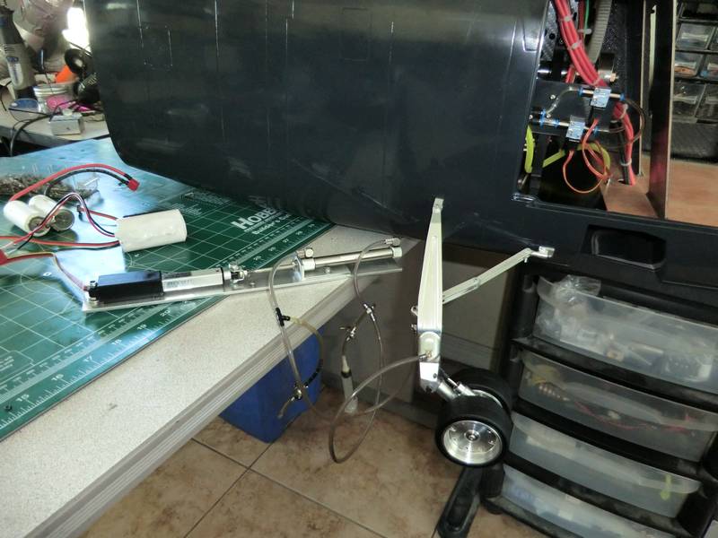
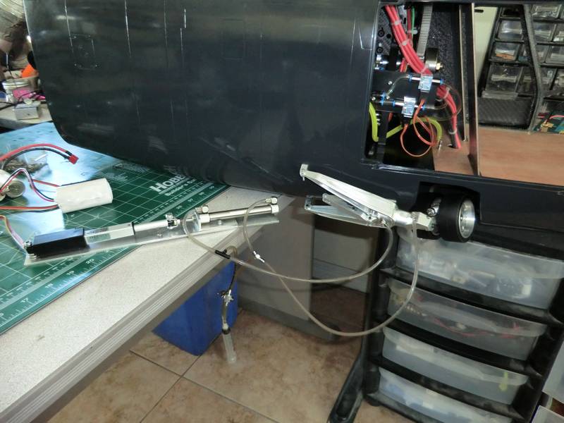
now I have to figure out how to get the hydraulic pipes through the fuselage wall, and to the hydraulic ram. I do have some bulkhead connectors and I'm going to try and fit those in line and see if they hold up to the pressure as they are only single barb. Then I am stopped on this model until the exhaust system arrives from Mr. Zimmermann.
I machined up some double barb bulkhead connectors and fitted those in the appropriate place, which was not a scale place, but it would've been impossible to fit them in the correct scale place due to the way the hydraulic pipes have run. This is all been removed from the helicopter and placed carefully to one side, ready to fit after painting.
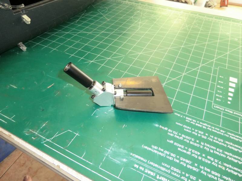
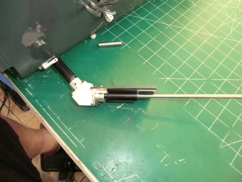
The exhaust pipe still have not arrived and I am getting somewhat frustrated with Mr. Zimmermann. He is not replying to emails, but he claims the pipes have been sent. So all I can do is give him a little more time to get them here. I have no idea how he sent them as he will not respond to emails asking for tracking numbers for shipping methods so the next thing to do is something I have been putting off deliberately. That is the tail drive. I know it's not going to fit, I can see that simply by looking at where the output drive is coming from in the turbine and the angle of the carbon fiber tail boom. So, some serious thinking was required, and that occupied valuable flying time. So I have been putting it off as long as possible, but today I bit the bullet, and got stuck in. The first thing to do was to make a precise coupler to go from the turbine to a 6 mm driveshaft and this would allow me to see exactly where the driveshaft arrives in the fin. So I bolted the tail boom in place, reamed a piece of 8 mm steel to have a 6 mm bore,and then I cut it down to size
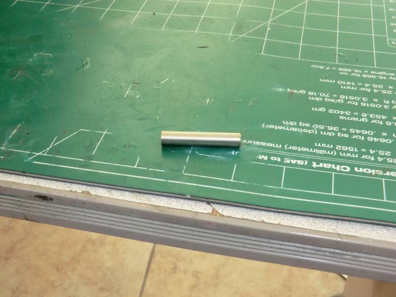
I fitted a driveshaft into the adapter and fitted it to the turbine.
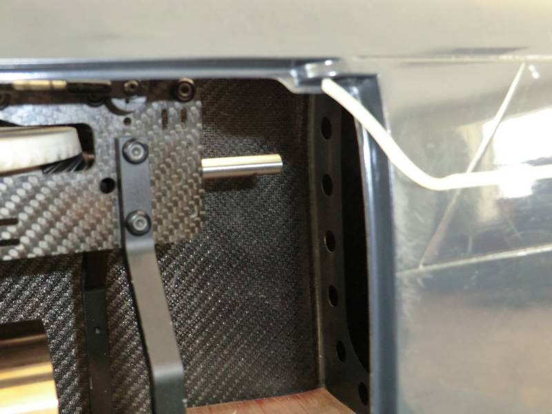
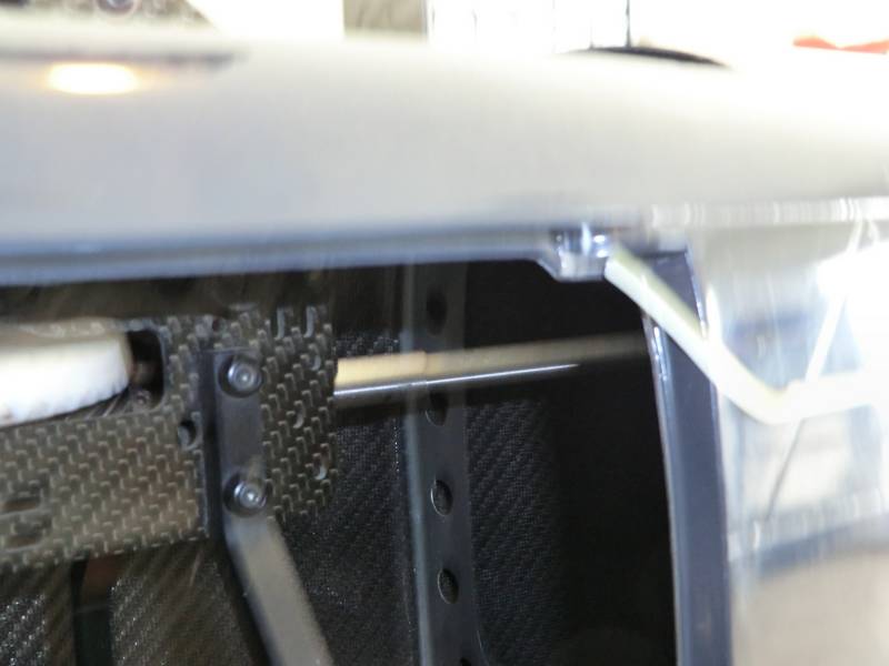
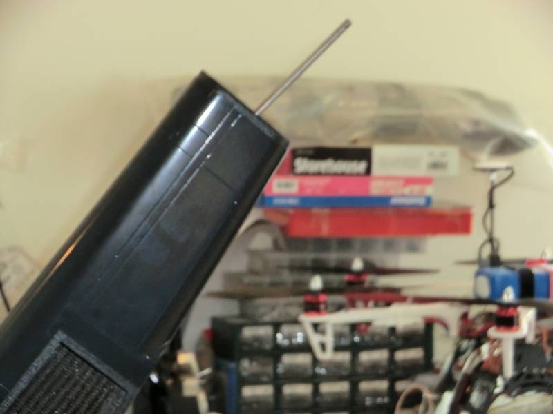
now I ran a piece of tape down the side of the tail boom so I could see where the drive shaft was going to run.
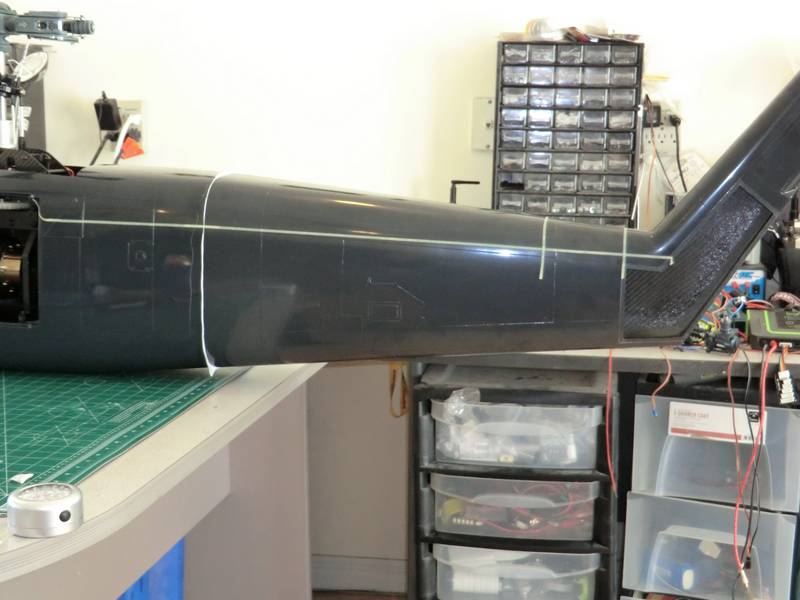
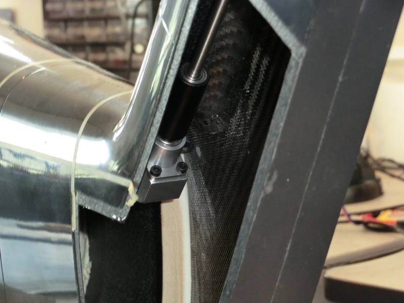
Ignore the white paper between the tail boom and the fuselage, that was one of my bright ideas, which turned out to be not so bright. Then I had to make up a carbon fiber plate to carry the OF gearbox. This is a new device in that the input and output connectors are one way bearings so you simply slide the drive shaft into the one way bearings and that's it, job done. However alignment has to be perfect but that is facilitated by the length of the one-way bearing holder which forces you to get it right, or you cannot get the drive shaft into the bearing.
Unfortunately, Gavin had put a bulkhead just before where I wanted to mount the carbon fiber plate, so I had to chop slots in that to get plate in place. Then it was just a process of sanding, filing and drilling holes in the right place to be able to get everything to line up perfectly.
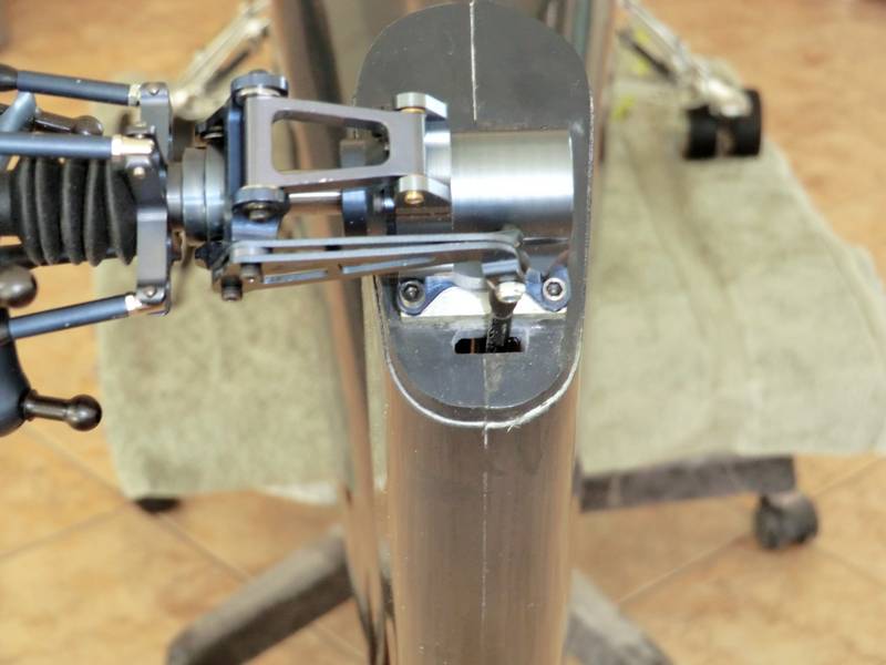
One thing which did not come out 100% perfectly was the drive shaft from the intermediate gearbox up to the top of the fin.. This means that I will have to machine up a plate mount to the top of the fin to allow the gearbox to be perfectly at right angles to the drive shaft. The carbon fiber plate is glued in place with epoxy, and when it is set up tomorrow, I will apply a lot to make certain that the plate doesn't move. Then the driveshafts can come out and they need to be cut to size and have pieces of steel glued inside them at the ends so that they do not get crushed by the one-way bearings or the dog bone coupler. Connecting to the tail rotor gearbox will be achieved by simply drilling a hole through the drive shaft and inserting a hardened steel pin in the hole to locate it in the slot in the tail rotor gearbox. More on that part when I get there.
this whole assembly will use a aluminum tail boom inside the carbon fiber tail boom and there will only be one dog bone coupler which will be the one which connects to the turbine. There will be no misalignment anywhere in the whole drivetrain, and so there should be no wear. At least, that is the plan. I have had my fill of steel dog bone couplers wearing out or needing leather inserts and grease to make them last more than a couple of flights.
Machining up the angle plate was trickier than I expected as I needed to drill an 18 mm hole for the tail rotor gearbox. So I started off with a thick piece of 2 inch diameter aluminum rod which I found in my junk box. I put it in the lathe and bored the hole to size. then I put it into the mill and cut it to size. This was the difficult part as, for some reason, none of my measurements came out correct, so I had to cut each side equal around the hole, measure the total width, and subtract half from each side. Then I had to mount the piece at an angle in the mill. I confess I did this by trial and error, and kept on cutting until the shaft protruded at 90°.
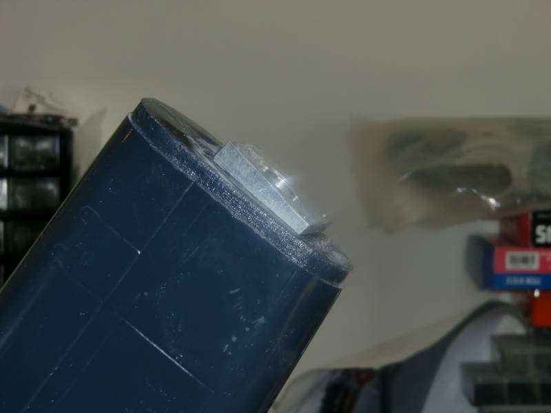
Then I drilled and tapped it using the tail rotor gearbox as a template but it was not until I came to fit it that I found the holes in the gearbox mounting plate were 2.5 mm and I had tapped the holes 3 mm. I had to drill out the mounting plate, and then machine the edges of the Allen screws so that they fitted easily. That will teach me to rush!
Now the shaft fits perfectly into the intermediate gearbox and into the tail rotor gearbox. There is more work to do on the shaft, but I am going away tomorrow so I have glued some blocks inside some 6 mm tubing to support it and will get back to it next week after I return from a trip to SEFF with Darrell.
The exhaust pipes have finally arrived. It took just over a month for them to get here from Germany but when I opened the box the wait was worth it. This is what I ordered. I hope I have enough parts but there is one missing from the photograph and that is the diverter that fits on the back of the turbine to split the exhausts to go around the tail drive shaft. That is on the turbine!
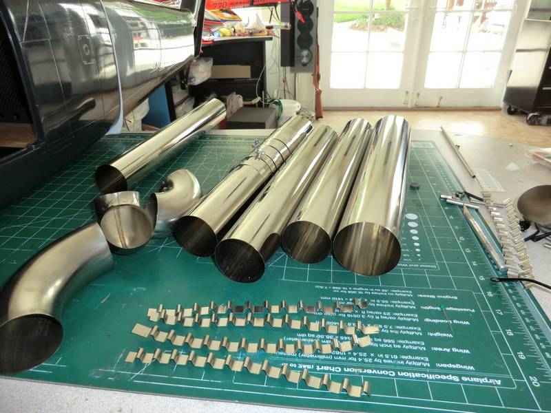
I have 2 large 90° bends 4 smaller ones, 4 straight pipes the same diameter, and one larger pipe. There are also several clamps and the wavy parts at the front are separators to allow the larger pipe to sit around a smaller pipe and make it into a Venturi to keep the pipes cool. The really nice part about this is that these parts can all be pushed together.
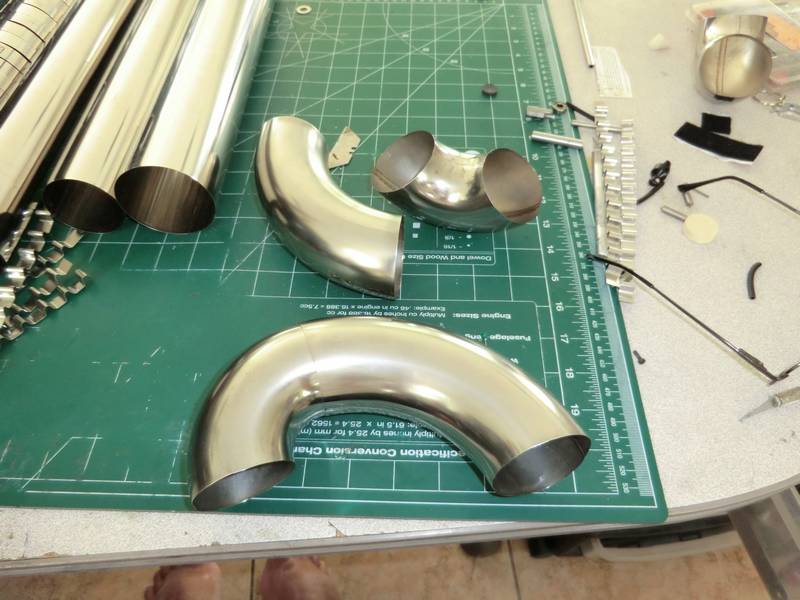
For example, I have pushed a small pipe into a large pipe at the front at the 2 parts are used are behind it. I can push them together even further to change the angle slightly. In my installation I will be joining all of the curves with straight pipes which is why I have bought a lot of them so I can happily cut them into small pieces and be sure I have enough do the whole job. Meanwhile the tail drive tube with bearings in arrived so I cut that to length and fitted strengthening blocks inside which are now gluing. Tomorrow I can check I have the correct length and then remove the tail from the main tub and then get to work on the exhaust which I am looking forward to.
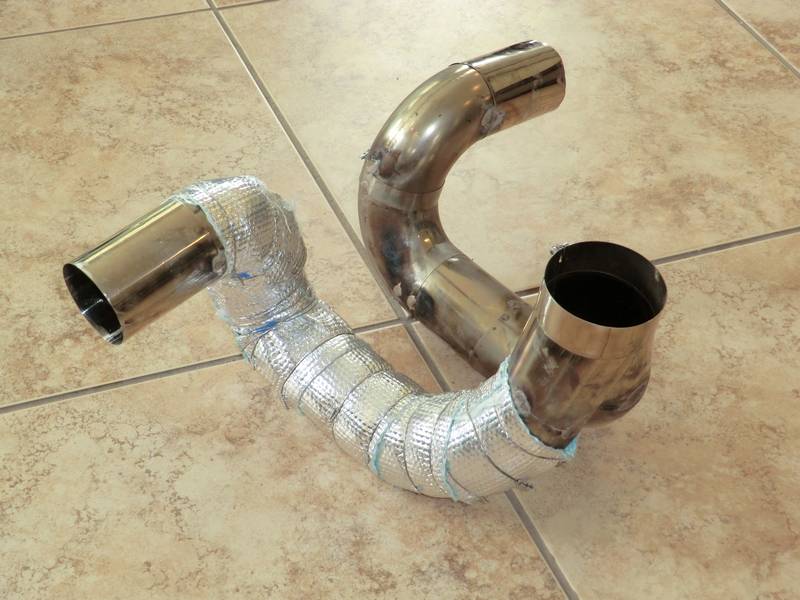
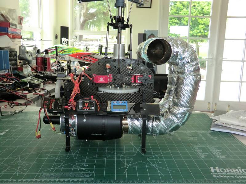
It has been some time since I updated this build. I have had several personal issues which slowed things down, and then I had to learn some new skills at this has taken some time as well. The first problem was to make the exhaust and I had ordered the parts from Zimmerman which took a long time to arrive and when they got here I found that they did not all fit together as I expected, but needed fixing together in some manner. The problem was that I had to create a butt joint with two thou thick stainless steel. This meant cutting part of the tubing which I had ordered extra of, and cutting a slice out of it and welding it in between the two parts to be joined. Rick Gonzales was kind enough to lend me his spot welder, but unfortunately he had made it to make a straight pipe. My pipe was anything but straight, so rather than modify his tool I purchased some copper rod and made my own probes. Again this took some time and was not entirely successful as the curves made it almost impossible to create a complete series of spot welds around every joint. I decided in the end that I would put a security weld with silver solder across each joint and this took time. Then I had to learn how to security wire around all of the insulation I was going to put around the exhaust pipe. I purchased a wiring tool and some stainless steel wire from Harbor freight and after trying it threw it out! I then purchased another tool from a motorcycle store which came with some wire which was obviously the correct size. So I started wrapping up the exhaust pipe. I need more wire as all I got was a small sample so it will be early next week before I can finish this job. This is how it looks so far.
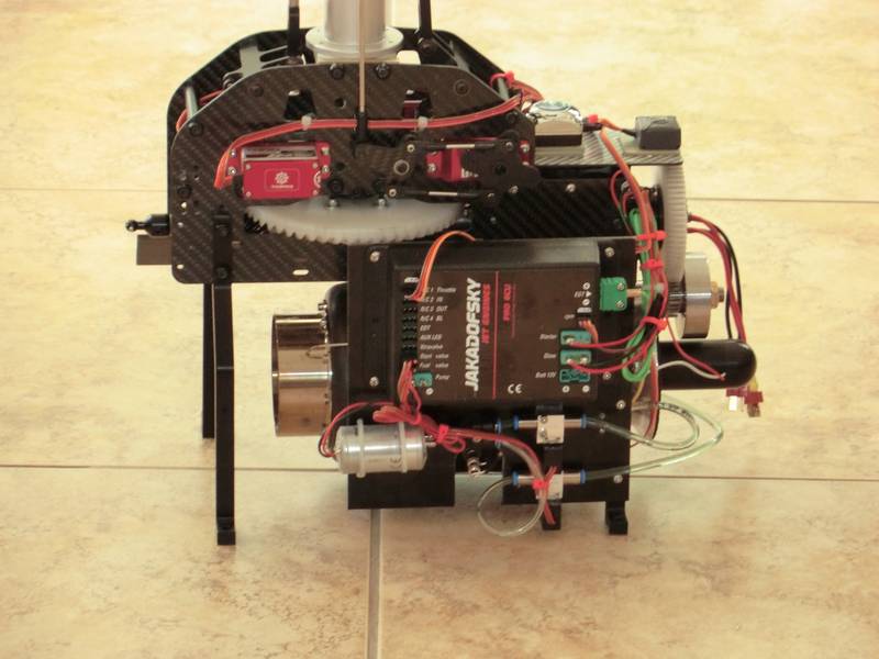
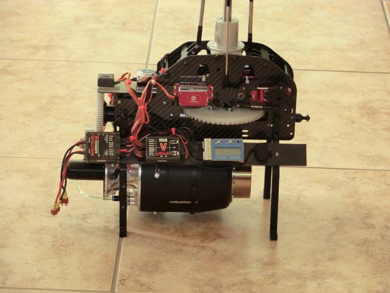
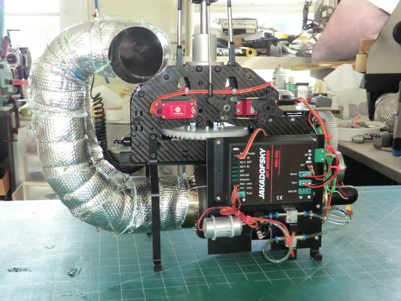
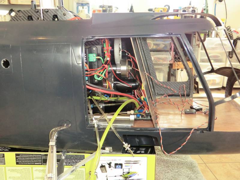
The other job that I wanted to do, became fairly obvious that it had to be done when I took the mechanics out. All of the electronics and control system for the turbine really needed to be mounted to the mechanics so that everything came out as one piece. I scrounged a piece of G 10 from Darrell who cut it to size for me and this allowed me to mount the oversize ECU that comes with a Jakadofsky turbine together with the fuel pump and associated valves. I used another piece of G 10 on the other side to mount the electronics but it all ended up being too wide to go through the hole in the top of the fuselage. So I had to rethink the electronics and found a long piece of carbon fiber which I mounted at an angle on the top of the mechanics legs and fitted the electronics to that.
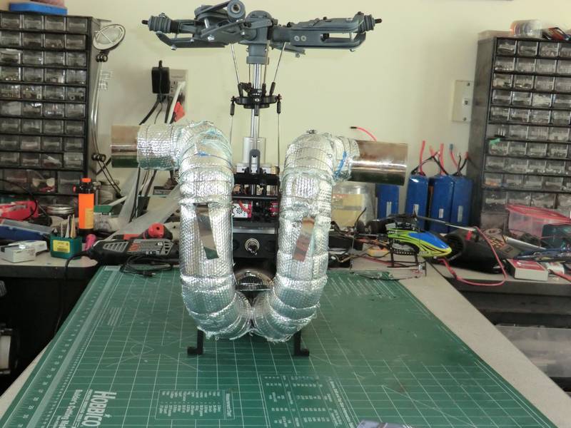
More safety wire arrived and I could finish off the insulation. But first I had to undo a little of yesterday's work so that I could weld on some tabs to locate the exhaust inside the fuselage. Then I went round and wrapped all of the exhaust and fixed in it place with the safety wire. Tomorrow, I will run the turbine up on one of my trolleys and make sure everything works correctly and see how noisy the exhaust is. Hopefully, cleaning up the outlets and removing the burrs will get the noise level down to an acceptable level. This is what it looks like all wrapped up.
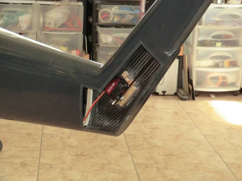
It did not seem to make much difference to the noise level especially on full power, and there was a lovely howl as the turbine was spooling up. There is nothing I can do about that so I am going to ignore it for now, but I feel sure nobody would ignore it when I fire it up. The next thing to tackle was the tail boom and tail rotor control and I decided to fit the servo in the fin. I first placed the servo onto wooden mounts in line with the tail boom. When I tried to slide the pushrod up-and-down it became obvious that I needed to move the servo so rather than remove the original mounts I just added some more. I also made them bigger so that I had options on positioning the servo.
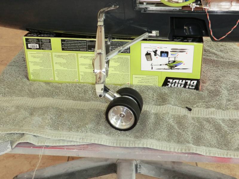
To cut a long story short, I fitted the landing gear and then screwed the mechanics in place. I did all the work necessary to get the exhaust to come out on the correct place in the nacelles. Then I fitted the tail boom in place. At the moment it is held in place with some bolts which come from the tail boom and go into the fuselage. Getting the nuts on from inside the fuselage with the mechanics in place proved painful! So I only fitted it with two or three nuts to ensure it was secure. At this point it became quite obvious that I would have to remove the mechanics to get the exhaust in and so I decided to cut everything short for the day but before I finished I put some PFM around the tail drive tube to accurately locate it in the wood former which is across the tail boom.The PFM will set to a firm rubber consistency and absorb any vibrations which are occurring in the drivetrain.
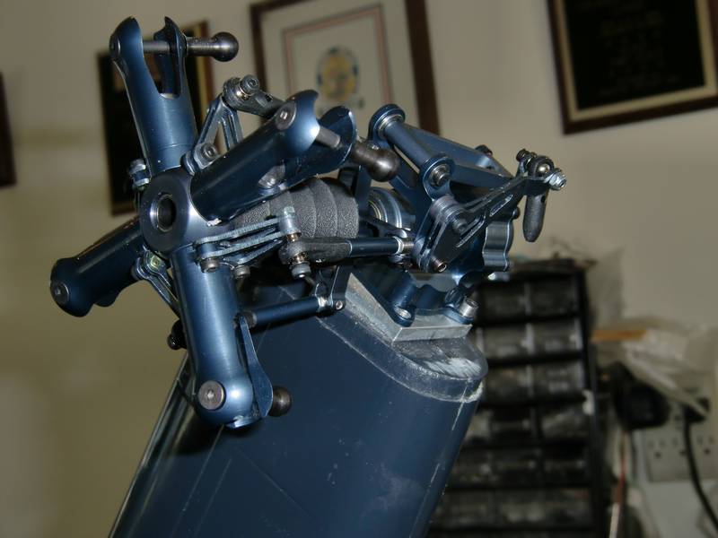
One job which became immediately obvious would have to go on the job list was the tidying up of this mess at the front of the turbine. However that can wait until later. I have left the extensions and the small shutoff valves in the hydraulics to the landing gear as I will have to pull the pipes off and the landing gear off when it comes to painting the fuselage time. So there is no point in making this a permanent installation just yet. Removing the excess piping and valves will make things a little tidier inside the fuselage. You can see how neatly it all fits together outside.
Work has progressed in a slow but sure manner. I ran into one or two problems which slowed things down. The first thing was that something seemed to be wrong with the rotor head so, that has been sent back to Germany but unfortunately Matthias is on vacation and it will be a week or two before I get that back. So I substituted the OF head which came from my EC 145. The OF head had a 6 mm hole in one side to mount it with a spacer to reduce it to 3 mm. The other side of the hole was 3 mm. Needless to say the hole in my main shaft was four millimeters. This meant Drilling the 3 mm hole out to 4 mm and making a spacer which would adapt the 6 mm hole to a 4 mm bolt. This done I can now mount the tail boom and put the mechanics in place.
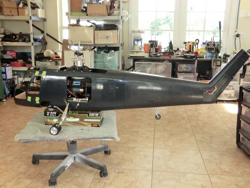
Once again I ran into problems! Firstly the tail boom is bolted on with 3 mm bolts and nuts and all of the nut drivers that I had were too long to allow me to tighten up the bottom nuts. A search through my socket set showed that I did not have a 5.5 mm socket but I managed to find some at Home Depot. Then I found that once the tail boom was on, the tail driveshaft prevented me from getting the mechanics in place. If I put the mechanics in I would have to put the exhaust pipe in as well as the driveshaft goes through the V of the exhaust. Then I would not be able to reach the bolts to tighten up the tail. This required some lateral thinking and in the end I opened up the doorway into the cabin so that I could mount the exhaust onto the turbine and then slide all of it forward into the cabin and drop it down onto its mounting plate and then slide it back into position so it coupled up to the driveshaft. This is how it looks now.
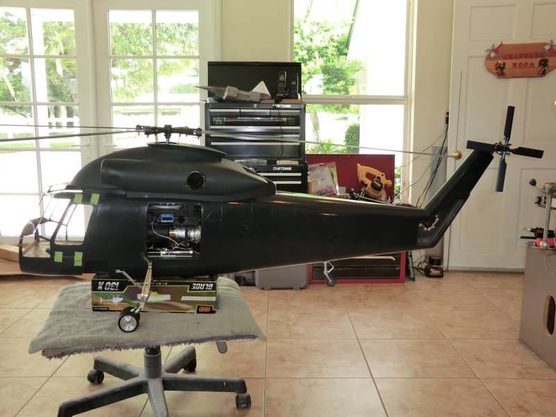
A lot of the mess has simply been tucked out of the way for the photograph and it will need to be sorted out before flying. The next job is to setup the the V bar, charge up the batteries, and fill up the fuel tanks. Then, I have to test fly it. This is the most nerve-racking parts of the whole build. However, I don't have to fly till tomorrow. :-)
Unfortunately, due to circumstances beyond my control, I have to suspend this build for the time being and and am going to start afresh , with an electric version.