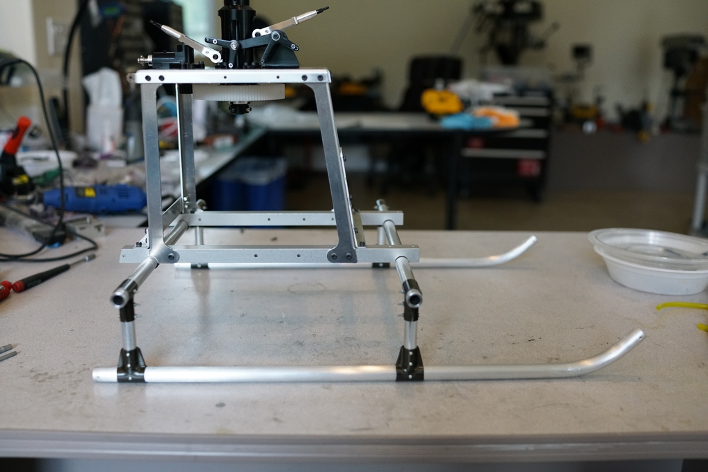
The first job was to assemble the landing gear, with 10,000 screws and that messed my hands up for a couple of days. Then the main chassis had to be built up and that had the same result. This is not going to be a quick build and I am not using loctite on items which will have to come apart to be painted or powder coated so it will be double torture taking it apart and then putting back together again.

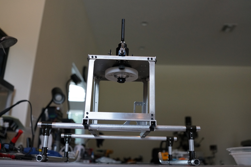
The main gear has an interesting adjustable torque limiter built in, I assume to stop you stripping the gear if you open the throtle too fast.
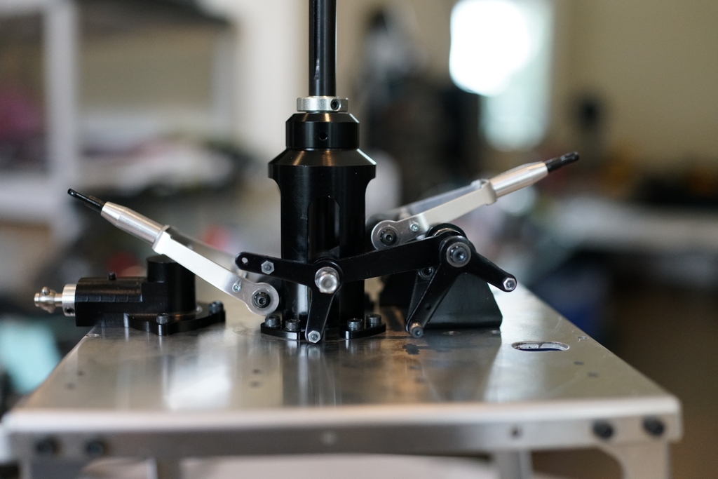
The control linkage is a pretty complex affair and part of it has to go under the mast extension so that was built up and the the whole lot fitted to the top chassis plate
I dont know anything about gas engines, but I do know this one weighs a ton and I am not going to use it. The first step in getting rid of it was to figure out what size electric motor I needed to replace it with. Reading through different pages of the manual I found they claim the gear ratio is 8.03:1 which is impossible as the main gear has 95 teeth so the pinion would have to be between 11 and 12 teeth. The manual casually mentions the headspeed should be around 1500 rpm so using a 12 tooth pinion would give me near 8:1 and I would need a 280 Kv Motor to drive it. Digging deep into the bottomless junk box I found this which just happens to be 280Kv
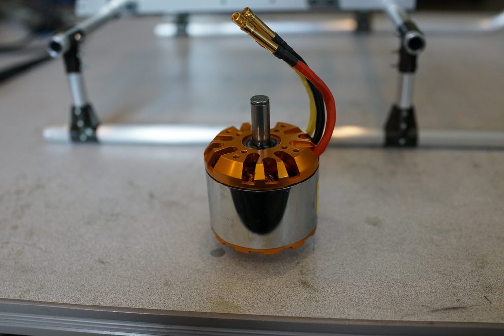
The motor is rated at 2100 watts, near 3HP, and I guess that is more than the gas engine could make so I should be safe for power. Now my problem is that the pinion I have ordered has a 6mm hole and the motor has a 10 mm shaft. I have some thinking to do about that one.
After a few says mulling over this problem, I decided the only effective solution was to use a clutch. This was for 2 reasons. Firstly there is no one way bearing in the drive train so autos would be impossible and even shutting the heli down would put a big load on the plastic gear. Secondly, I couldn't hink of any other way to drive the main gear without a major redesign, probably using a Goblin double reduction system. This would leave a lot of unused holes in the top plate.
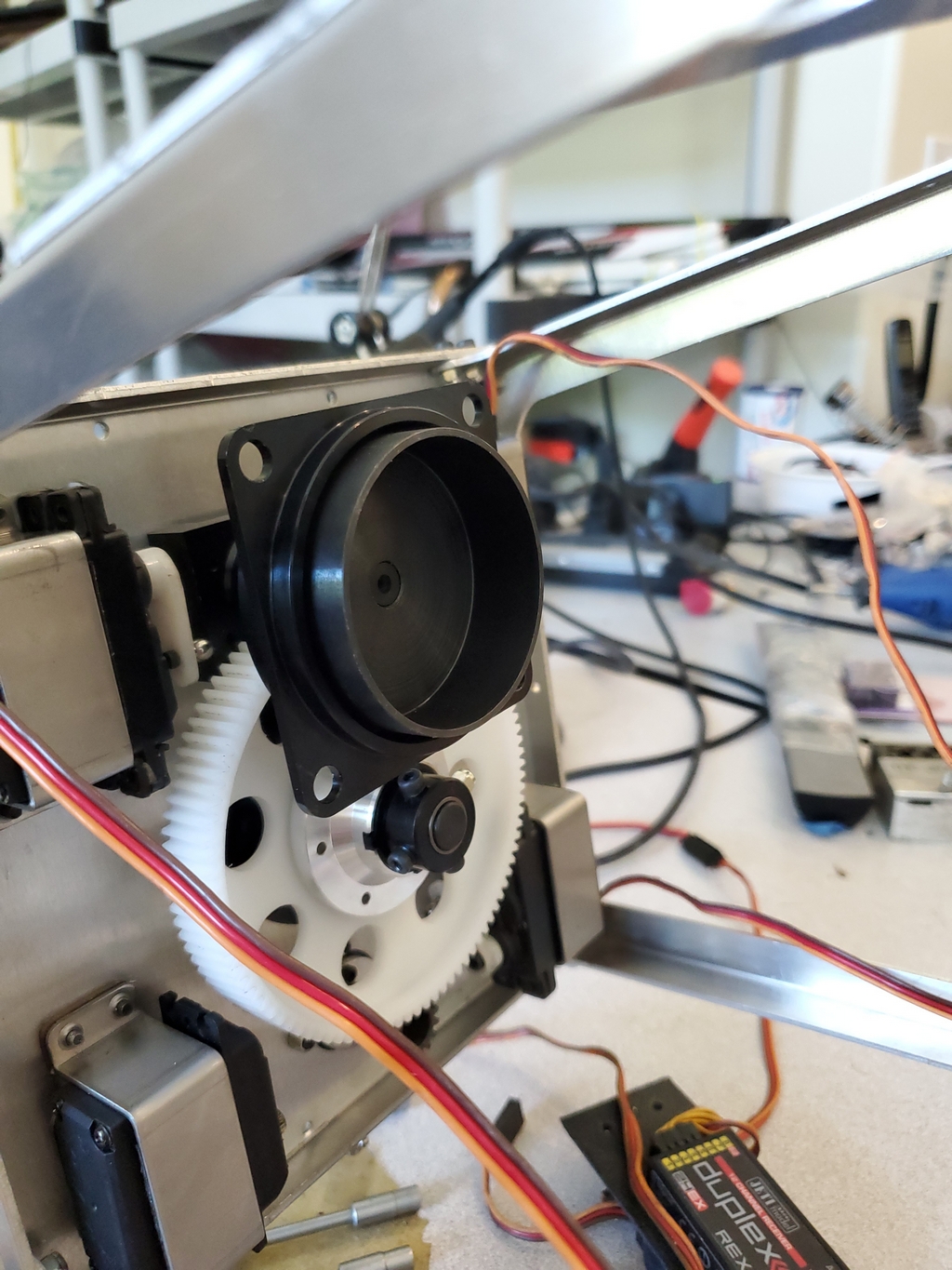
Vario make a 45mm clutch for the benzine trainer which would work, and the liner makes it up to 48mm diameter. The bell is 55 mm inside diameter so I would have to machine up a spacer to fit between the bell and the clutch liner. The clutch will have to go in upside down and be held by one of Darrell Sprayberrys clutch adapters. He is already set up to make them and it would be much easier than me turning one on my lathe. Yeah, laziness comes into it as well...
I have a 305 Kv Axi motor and I bought a 380 kv one as well. (should have checked the bottomless junk box before spending the money) They are smaller and lighter than the one in the picture and make more power. This will save me having to machine down the motor shaft to fit the clutch. I am going to make a motor mounting plate and some spacers so I can bolt the motor to the square plate above the clutch. That's the plan anyway
After a chat with Joe Howard the plan got changed! Joe did not have the clutch liner but he did have a complete clutch bell with pulley. That made me dive into the bottomless junk box to find 2 clutch bells and one unused clutch. I also looked into the AXI motor box and found this collet.
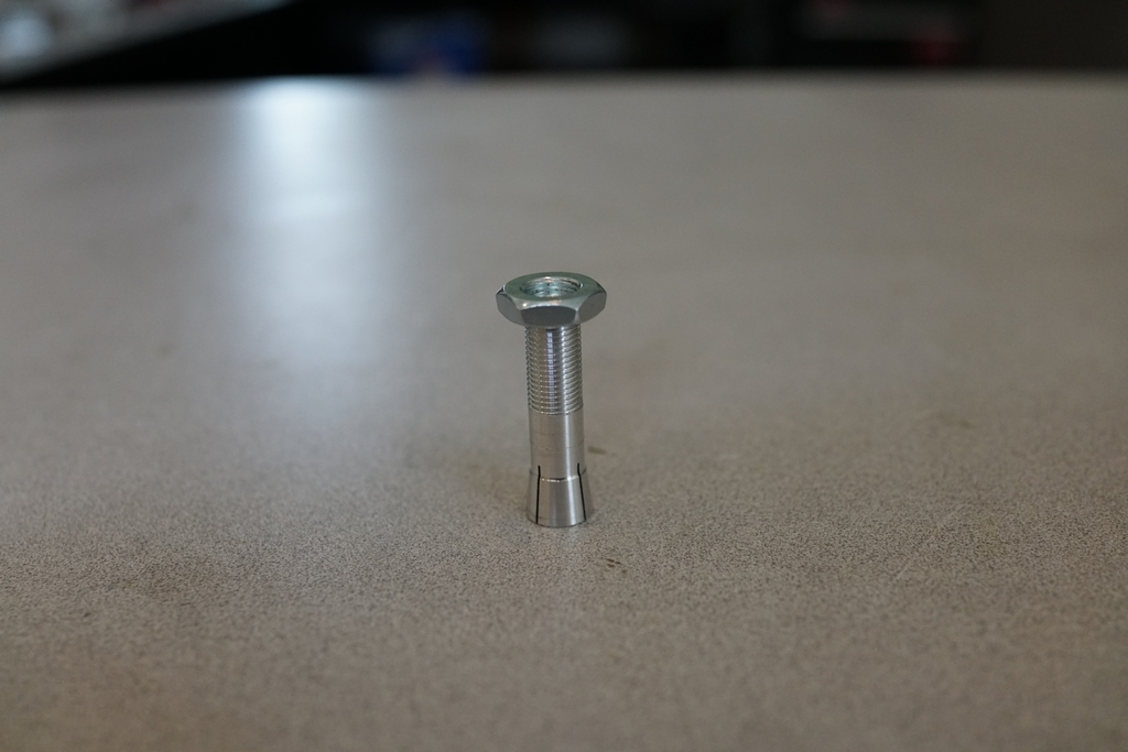
This fitted the Vario clutch perfectly, but the threads did not go down far enough
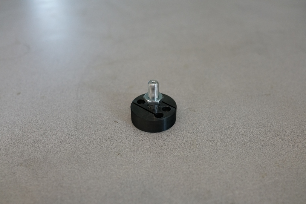
This gave me a problem. I had to run a die down the threaded portion for about 10mm and I could not see how to hold the collet. When I started I found the die was even tight on the threaded portion so was going to really work cutting a new thread at the bottom. This required a lot of out of the box thinking but I got it done eventually. Then I made up a motor mount from a piece of 3mm aluminum. This is how it all went together after trimming the collet to size.
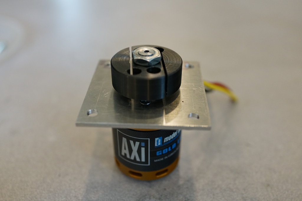
It was important to keep the height above the clutch as small as possible as it was going to sit inside the Hirobo clutch bell. I got a piece of brass shim and made a spacer to fit inside the Hirobo bell, so that the Vario clutch bell was an exact fit. I had taken the bell and machined the pulley and top off the bell so it was just a tube with the liner in it.
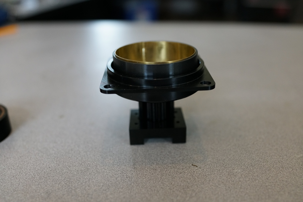
Then I had to commit myself to fixing it all together. Once glued in place with BVM Aeropoxy there would be no way to adjust it. It had to be right first time, with the tip of the collet clear of the Hirobo bell but the clutch as far into the Vario bell as possible, measure 16 times, glue once. It was also necessary to get the Vario bell perfectly aligned so it ran true otherwise mega vibrations would occur.
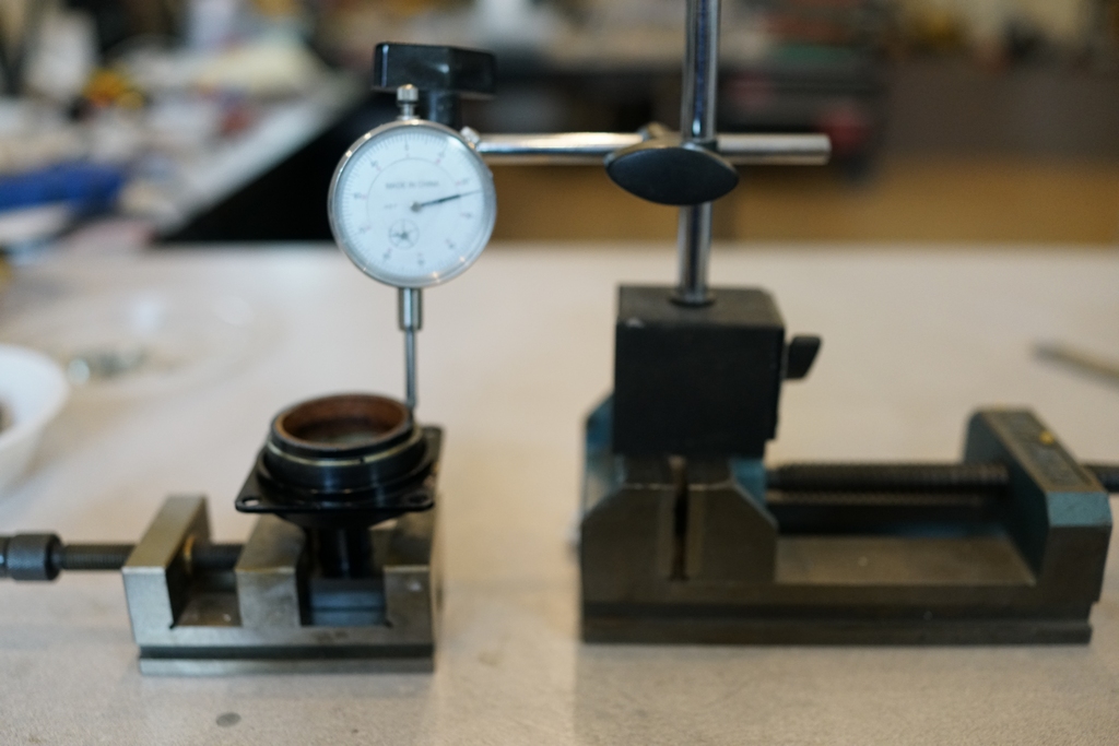
When the glue was set, I did a final check and I had got the run out down to less than 1 thou.
Now came the hard part. Machining the spacers. Actually doing it wasn't hard, except I had my Grandson Marcus do it and he was not too familiar with lathe work. To give him full credit, with a little oversight from me, he got all 4 spacers within 0.1mm. I mounted it all up inside the mechanics and this is what it looks like.
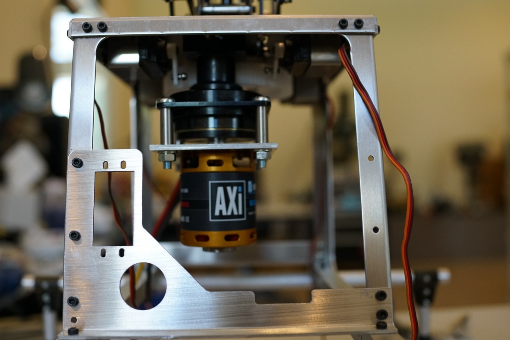
The clutch was still tight in the new liner and when I turned it, I was surprised to find that there was a one way bearing after all. It was inside the main gear, but it meant that in an auto, I would lose tail drive.
Now to take it out and loctite the spacer nuts. Then I have to preset the servo arms before replacing the motor
Servo arms are set at 90 degrees, and the linkage made up and installed. A very complex system and a lot of work, but not very exciting.
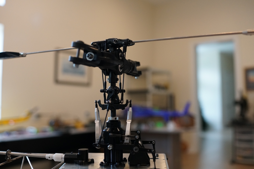
Adding the tail boom was a tedious progression of small nuts and bolts which were awkward to get to, and large nuts and bolts which needed 3 hands to fit. Nothing exciting here either
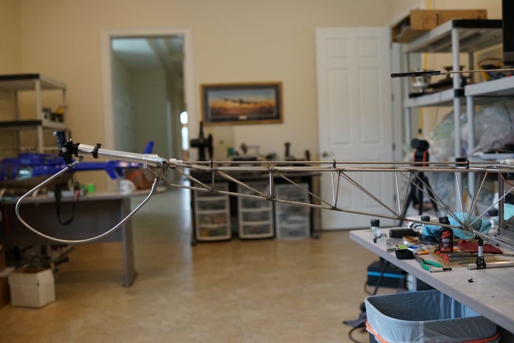
Finally, it was time to make something move so the Rx was wired up, a Hobbywing ESC fitted and a couple of 6s batteries connected. Firing it up was a bit nerve wracking with that flybar whipping around, but all was nice and smooth. That was exciting! The hammer hanging off the front is there because the brackets holding the front of the mechanics are fitted with the cabin so it needs some ballast to hold it in place
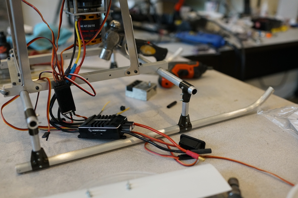
Now to sort out the tail linkage. It has a carbon fiber pushrod and a stainless steel tube, but the end of the CF pushrod has been split at some time and I doubt a replacement could be bought
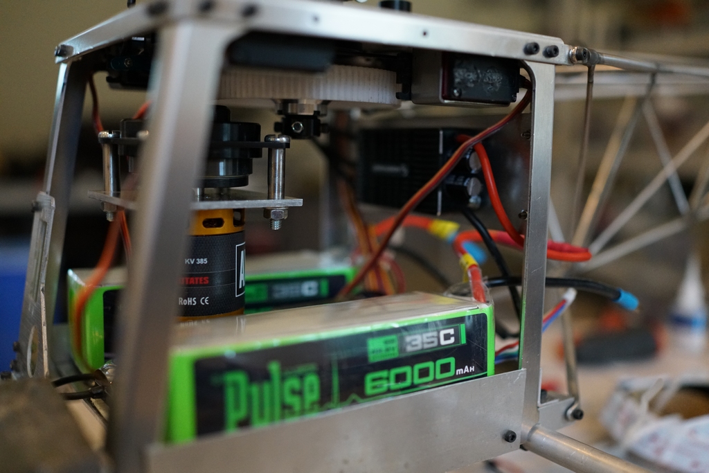
Fortunately the pushrod was some 6" longer than I needed and so I could cut the split end off and glue on the steel ball link adapters and it was the correct length. Looking at the picture of the motor assembly, you might think there was plenty of room to fit the rest of it especially as the servos were mounted above on the top plate. There isn't! I have fitted a couple of temporary side plates to stop the batteries falling out and installing them showed me there was definitely a shortage of room. I made up another back plate to hold the ESC and then fitted the Rx and gyro between the batteries. Its tight and I am not happy. I will probably have to put the Rx and gyro controller in the cabin under the floor so it became more important to get the settings right as they may be difficult to access. I have not looked at the instructions or parts for the cabin yet.
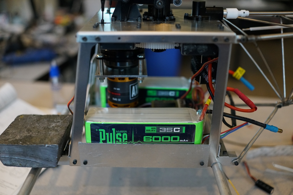
You can see the ESC on the back, even though it is well out of focus
Adding the front window made all the difference to the looks
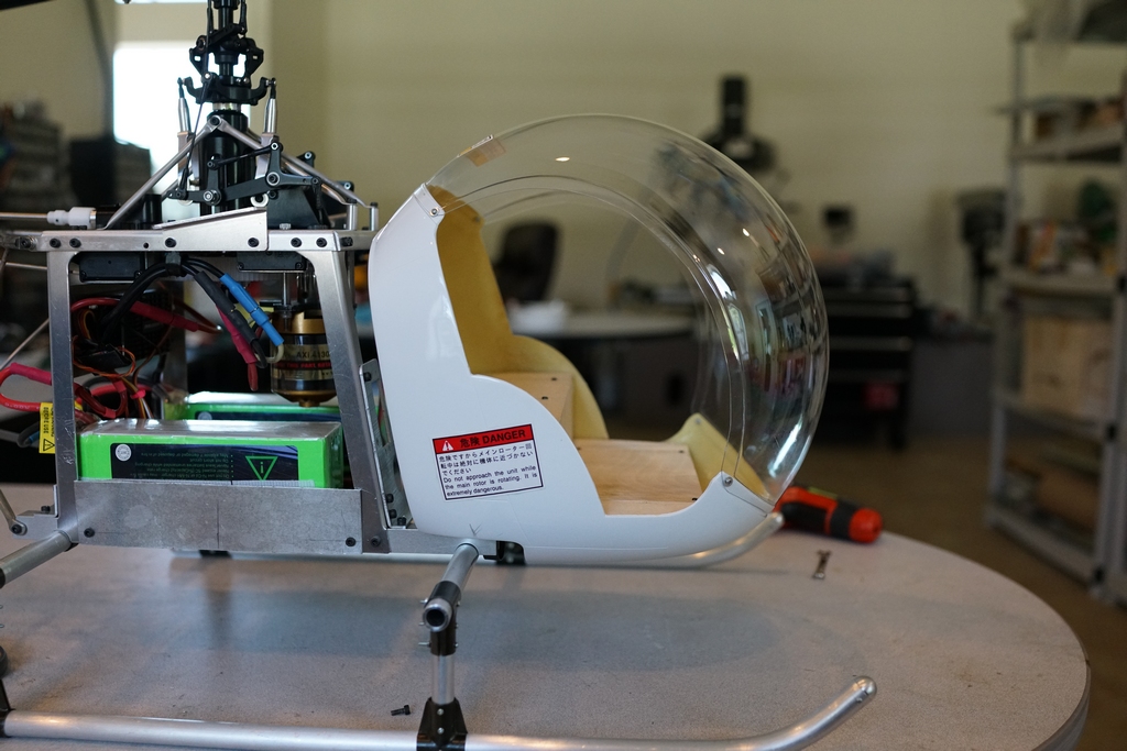
Time for setting up. Remembering how to set up a complex flybar setup was a bit of a challenge but I got there in the end and so it was outside to my test hover spot the check it all out. The head speed was nice and comfortable at 1350 rpm, and a few clicks on the trim settings had it in a nice stable hover. The next day I took it out with Marcus and had it doing its first circuits and it was really nice to fly, if a bit noisy in the transmission, but that was expected as it is a single reduction gear and is straight cut. Old technology.
Then I got an e-mail from Jon tanner, editor of the late Model Helicopter World magazine. He had been keeping an eye on my progress and explained he had also done the same thing, ie converted a gasser 47G to electric. He said he was using 34 Amps at 1140 rpm. Questioning him, it revealed that he was using 800 mm blades. I had briefly tried these on my model and was pretty sure there would be a collision between them and the tail rotor. Also reading the manual said that the blades could be turning at 1500 rpm so stay away from them while they were turning or they might make your eyes water if they hit you. So I went with 700mm blades. I never even checked the blades which came with the kit as they were wood and I had no intention of using them. So I stuck a set of SAB 2D FAI 800 mm blades on and sure enough there was about 20mm clearance. So I knew from my setting up on the 700's that throttle setting of 60% would give me 1100 rpm so I set it up at 60% and went back to the hover patch. It ran at 800 rpm. Adjusting the throttle curve managed to get me in the ball park, but on lift off the headspeed was varying all over the place. Either the clutch was slipping or the collet on the shaft was. So I decided 1350 was good for me, put the 700's back on and wound it back up to 1350 rpm and the clutch was still slipping. Obviously I would have to revise this and if I was going to do it I was going to go to 1100 rpm.
So I took a leaf from Jons book and made up a bottom motor mount to fit to the motor and 3 45mm tubes to act as spacers. His motor had an 8mm shaft so getting a 12 tooth pinion drilled out to 8mm cost him a lot of money and did not have much meat left, but apparently it was enough. I had a 300Kv motor with a 6 mm shaft and I could fit the pinion on directly. The shaft was not long enough but 10 minutes on the lathe had one that was way too long and could be cut to size. The major hurdle was the nut holding the other side of the elevator mount. Hirobo had suppled a top bearing block with a slot cut in it to clear the nut and that is why I wanted to use the clutch assembly as it was an integral part of the drive system. Jon elected to remove the nut and bolt and countersink the hole underneath and then replace the bolt with a countersunk one from underneath. Then he sourced flat bearing bock to go in there and had to drill and tap the mounting holes, ensuring the gear mesh was going to be correct when the pinion was on the motor. Had my model been all apart I would maybe have done the same but I was trying to do this with the mechanics all assembled, so I got to work on Solidworks and printed out a replica of the top bearing block complete with tapped holes. This positively located the motor shaft. It was a big struggle to get the holes for the pillars in the right place as one of them fouled the elevator linkage or didn't fit somewhere else. I decided to drill the 3mm hole out which mounted the elevator linkage to the top plate and I made it 4 mm. I had to put the motor mount in the mill to make the 4mm mounting hole a 4mm slot but it reached perfectly
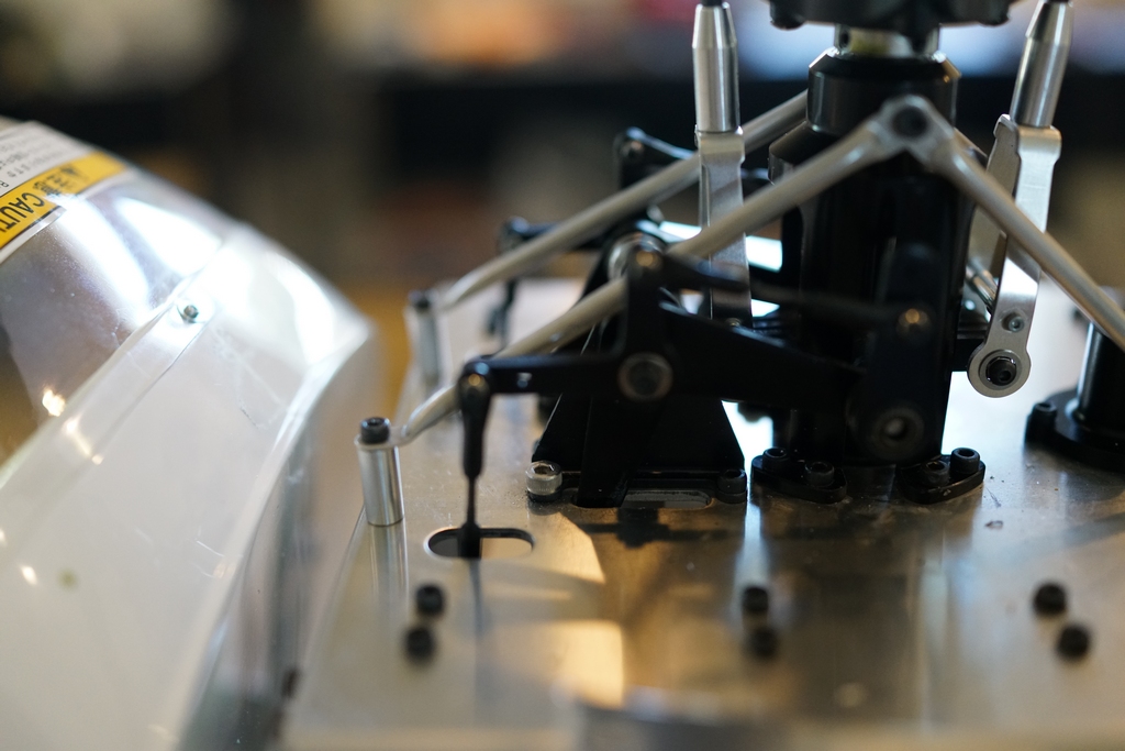
The pillar on the other side was comparatively easy as I could see it from both the side and rear to ensure it was vertical before drilling. The one at the front was a little off fore and aft but right side to side so its mounting hold became a slot too.
This is what it looks like now.
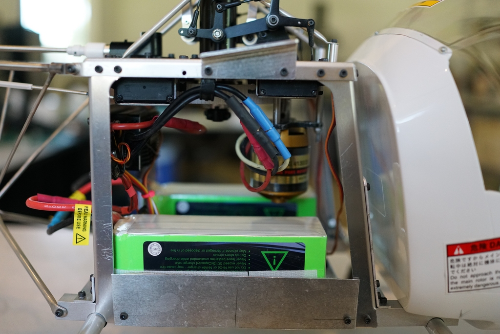
And the other side
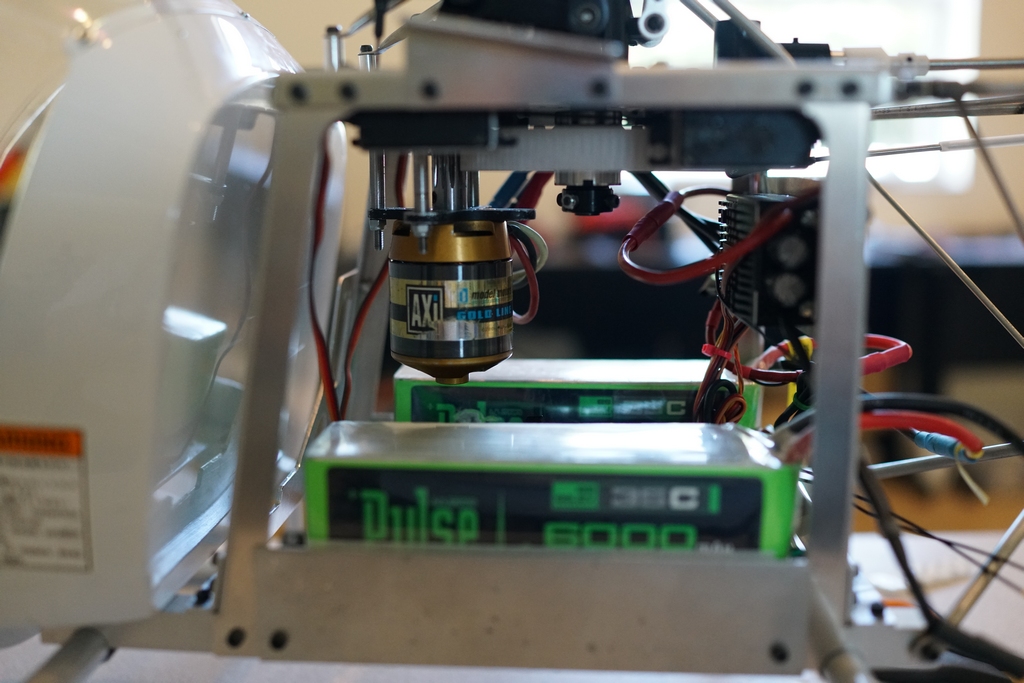
I did have the gyro sensor on the top of the mechanics as I could not mount it on the bottom plate without the motor interfering with it. I decided to mount it under the mechanics right at the back so it would be well away from interference. On my next test flight i found that mounting it upside down also meant I had to reverse it. That too 1 nanosecond to find out.
Finally I fitted an MUI sensor to monitor current and voltage and was very surprised to find it hovered using 16 Amps and punishing it only took it up to 20Amps. Several flights can be done on one set of 6000mAH batteries. Now my dilemma is whether or not to take it apart and paint it. Jon had stuck some tape on his and left it in bare metal and frankly it looks quite nice like that. I'm going to fly it around for a while before I make up my mind. I still have the cockpit to do and the fuel tanks and vertical stabilizers to fit and they will need painting regardless. The rest would get powder coated.
The Vertical tabilizer is fitted together with its braces and the end tips on the horizontal stab are fitted as well. Getting that right took the best part of a day
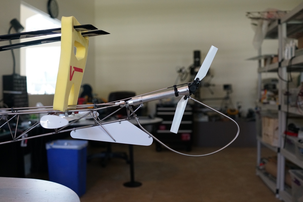
Another day was taken up fitting the fuel tanks, and trimming the joint. Still lots of pipe work to do on them and of course they need painting. I also painted to hopper tanks and fitted them with a crafty set of magnets, idea of Mr Tanner again, but I had to change his design. The bottom plate sticks out like a sore thumb now, so I will have to rethink that.
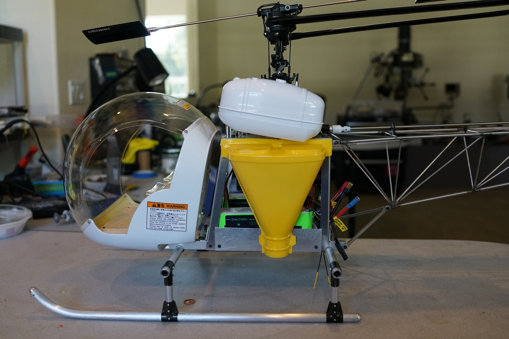
Plenty of room for batteries and because the tanks are on magnets they can easily be removed to fit them and wire them up.
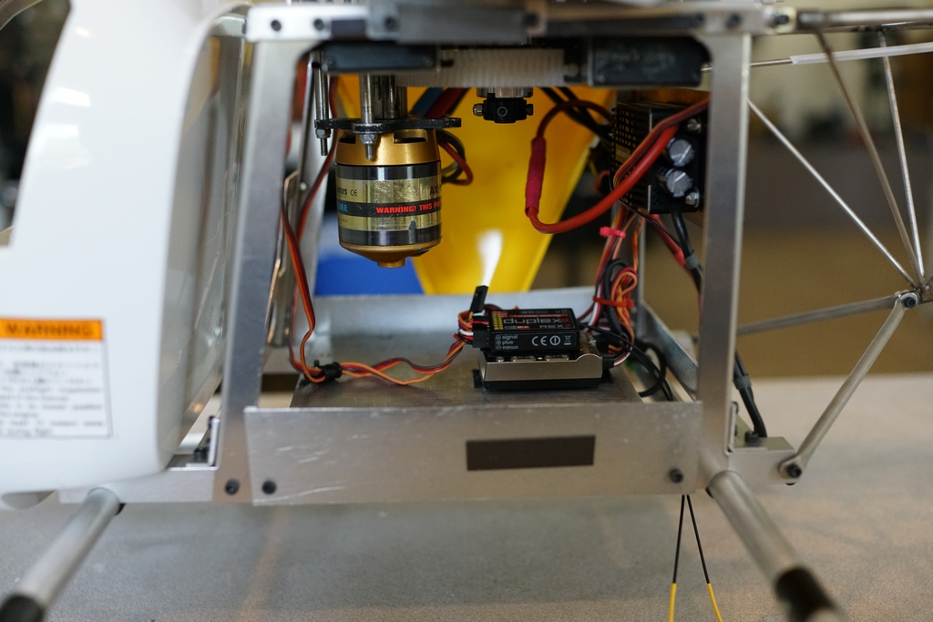
So this is what it looks like so far. The cockpit is next, but I keep on flying this thing it is so nice, it may be a while before it gets done. I am having second thoughts about the powder coating and may just leave the stainless steel untouched and paint the plastic. That will be red.
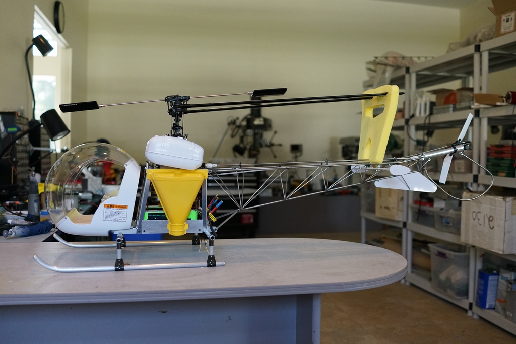
So after a ot of deliberation I decided to paint the color scheme of a helicopter I found on Airliners.net. OK, my wife told me to paint it that color!
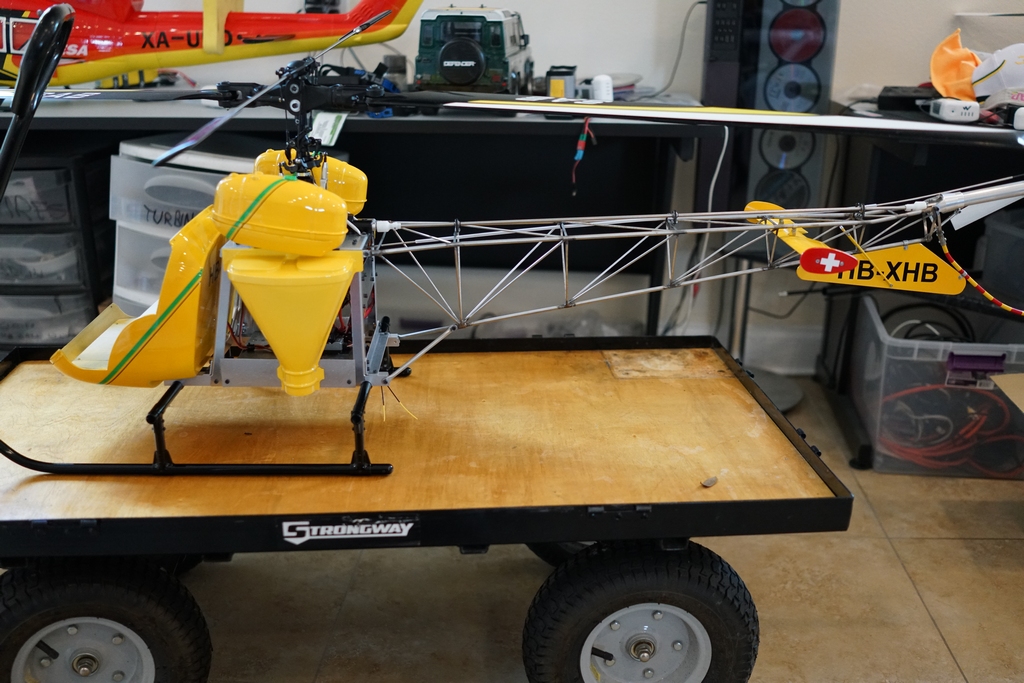
The yellow was straight forward, but the green stripe and black line proved to be less easy. I painted the cabin first and then clear coated it. Once set hard, I could mount it onto the frame and landing gear and then mount the fuel tanks so I could line the masking up so that the green appeared to be a straight line
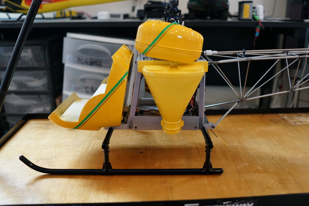
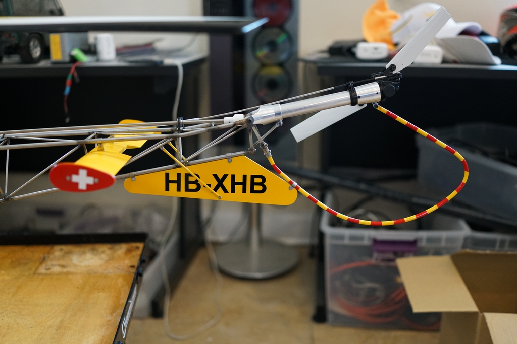
Then a splash of red on the small vertical stabs with the Swiss white on red cross, and more clear coat before final assembly.
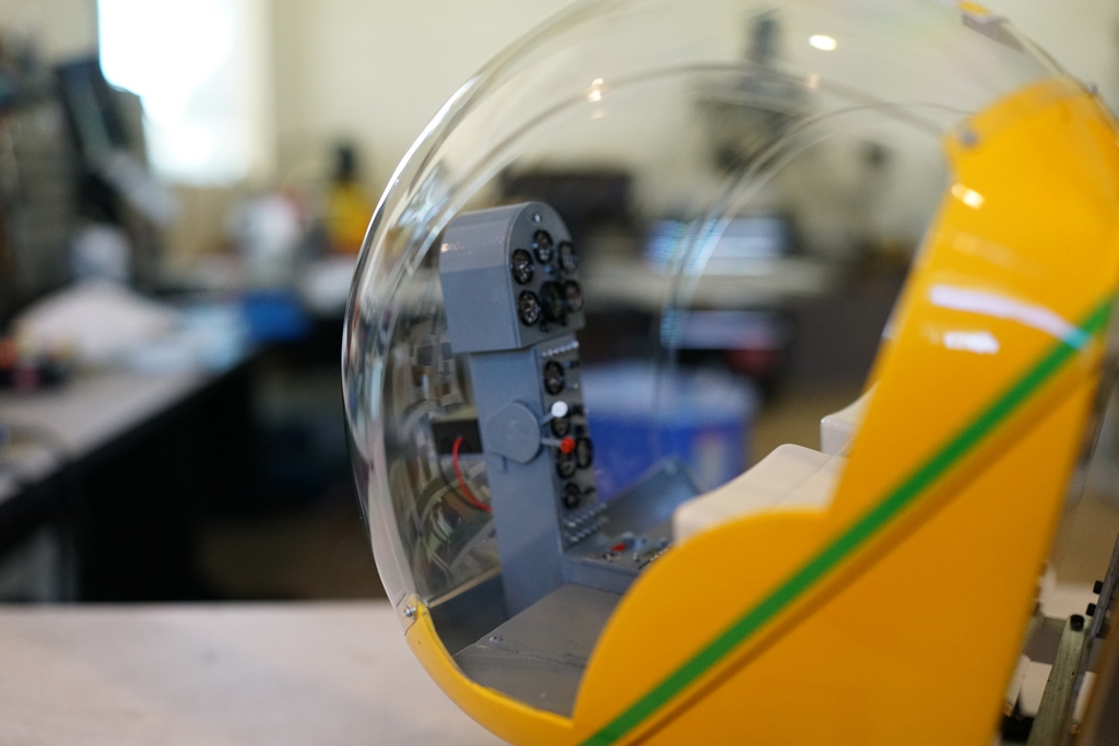
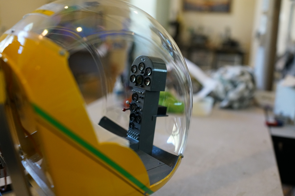
Then came the dreaded cockpit! The full size seats were sheepskins and I figured off white would be a good simulation. The one thing about the Hirobo 47G is the cockpit is all wrong, designed around 80's electronics and a gas motor air inlet. They had glued much of the wood work in place and changing it would probably have destroyed the cabin shape, so I made the best of what I had. So I painted the seats inside the clear plastic molding ,after some crazy masking of course, and they turned out pretty good. Then I got to work on the instrument panel. I had a piece of Balsa which was the main column and a load more pieces to make boxes to mount mechanical gyros and receivers together with batteries under the floor. I covered 3 sides of the Balsa column with thin styrene, and then designed a panel to fit. I made it with holes for the round instruments and sperately designed and printed the outer bezels so they could be painted black before fitting. The throttle and chcke controls have 1mm thick arms separated by a 0.5 mm spacer. Tricky printing stuff. While it was printing, I designed the appropriate upper panel for my model and when that had printed I was worried it would not fit in the bubble, but it did. Then a battery box was made, with a couple of wires from it and it was off to the spray booth for paint. Meanwhile my printer cutter was chewing up vinyl pretending to print and cut instruments. I made a piece to go from the panel along the floor to mount the radios as the full size but I didn't really have good pictures and the woodwork as fitted by Hirobo made it all wrong anyway. So this is one you wont see winning the Nats, but I like it.

Some 10" pilots are flying in from England, courtesy of a few tips from Glen and they will be belted in when they get here. I also want to add a few extra details like fuel piping and what looks like a loud hailer underneath but my printer needs a rest and so do I. A new high powered computer is coming next week so everything will be installed on that. Plenty of small details to do. As they say, a scale model is never completely finished