Electric Seasprite part 3
Now it is time to start assembling all of the parts which came wit the kit. The first thing was to fit magnets to all the doors. They should slide but have been made with large side panels and fit totally flush rather than proud of the body. As i will not be opening them except for service, I decided to fit them permanently and make up some dummy runners later. The back door has the window marked in the wrong place so I had a blank one made so I could cut the window in the correct place and fit the sonobuoy ejector as well. On the full size I am modeling, this door has been sealed closed
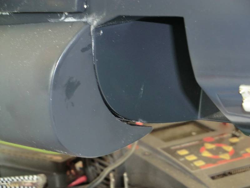
Then came the front cheeks. These are bolted to the fuselage on the full size and there is a distinct gap between the cheek and the fuselage. I simply glued thin flat magnets to both the body and the cheek and that gave me perfect separation. I wanted them removable as I have to fit various antennas, boxes, lights and steps to them so they need to come off to be worked on and for painting
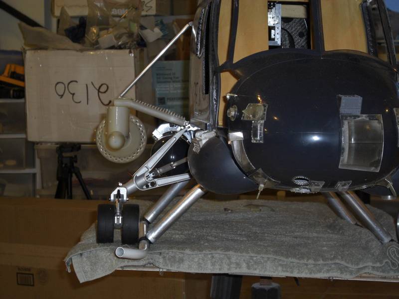
Studying the pictures carefully, I figured that the short fuel tanks supplied were the wrong ones and I needed a long fuel tank. This was done as the location for the second tank was occupied with a torpedo!
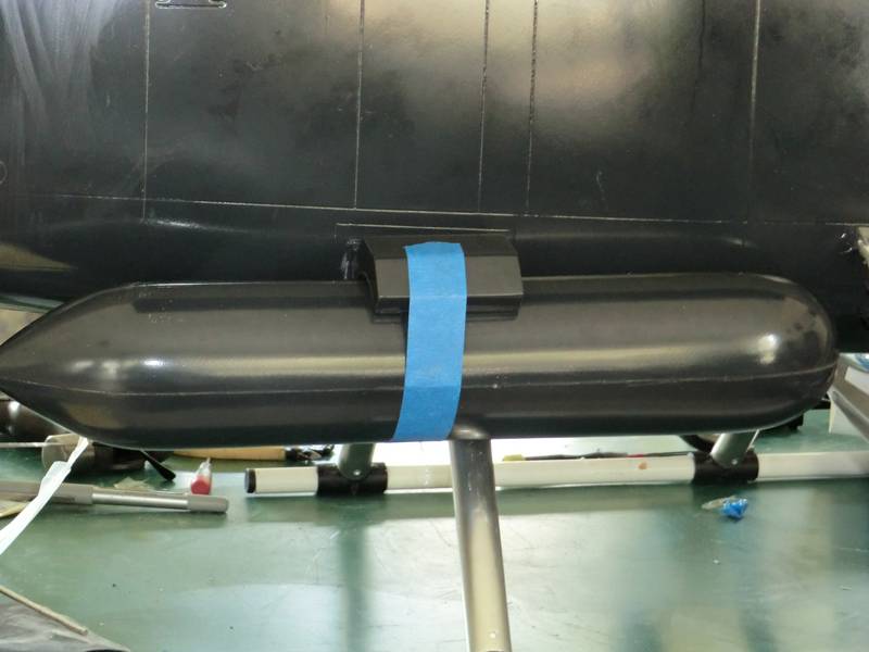
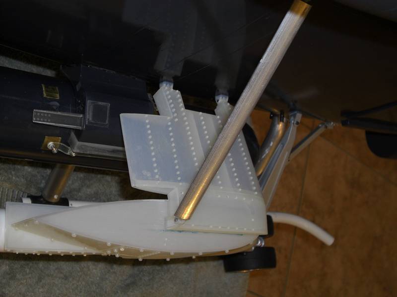
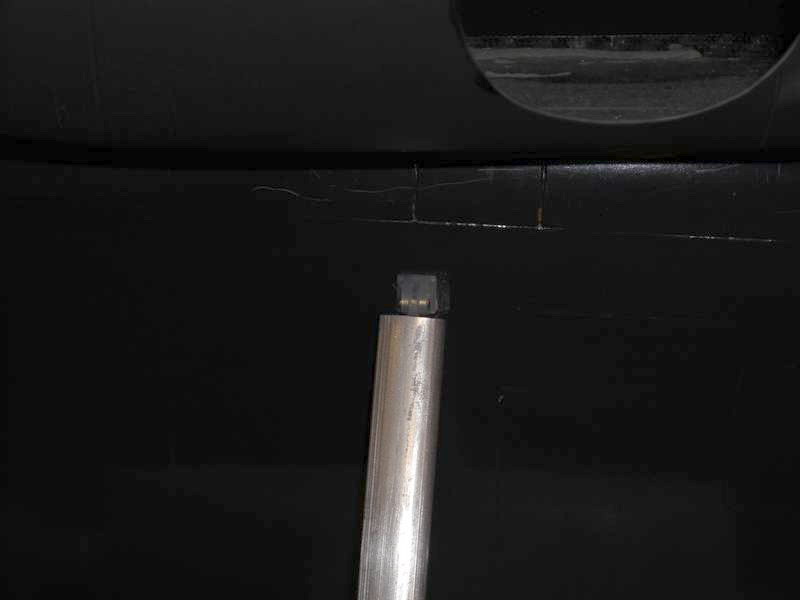
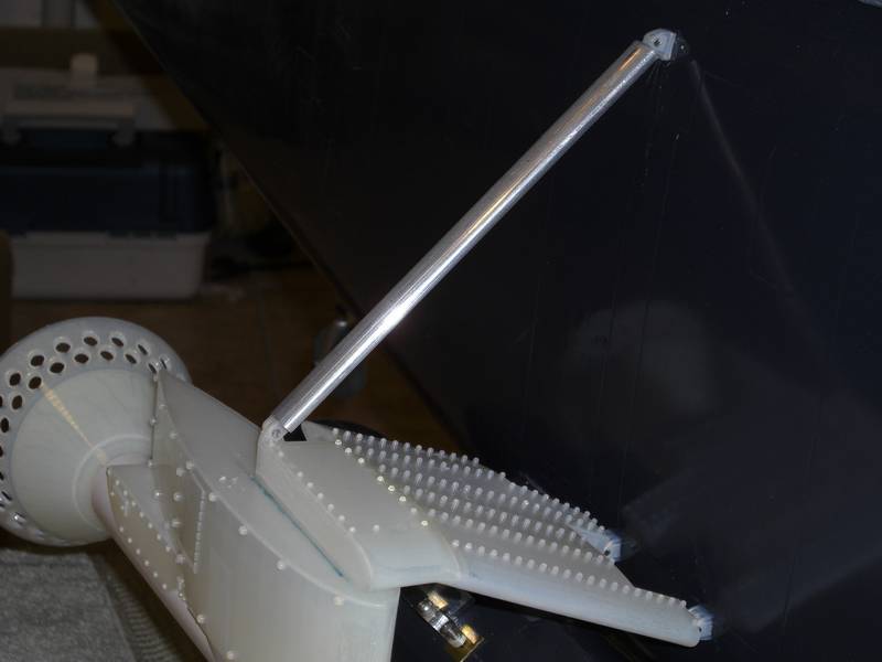
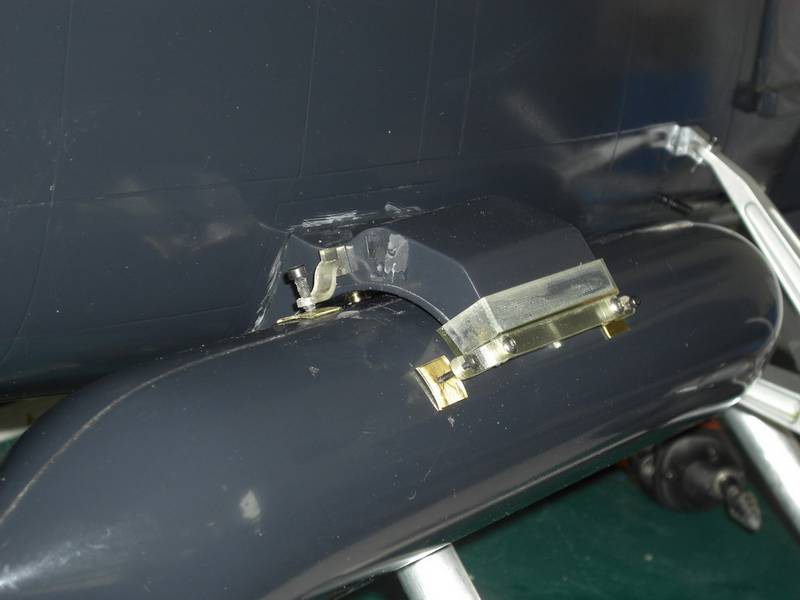
I have to make up a mount to attach the tank to the support, and after some thought, decided to attach the mount to the tank and attach the tank to the support with magnets so I could remove it for transportation.
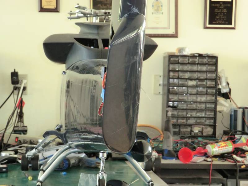
The last part to glue on was the angled section of the tail fin, so that was carefully lined up and taped in place
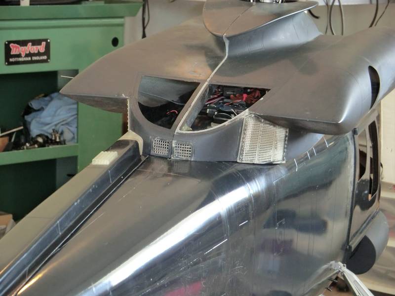
A weeks work did not seem to have much to show for it, but I was back on my computer with Solidworks and my 3D printer. I learned how to make louvers and I made the side vents for under the dog house top. I cannot imagine how I would make these parts without the printer. These are the side vents. They dont look too impressive as they are as I glued them with CA and as they are transparent, some of the background looks black, some white where the CA has fogged the inside,and some clear where the glue was not put. It will all look great with a coat of paint
The center louvers in the transmission tunnel
The rear vents and RH side vent, which looks very crooked from this angle
And the RH side vent from the side
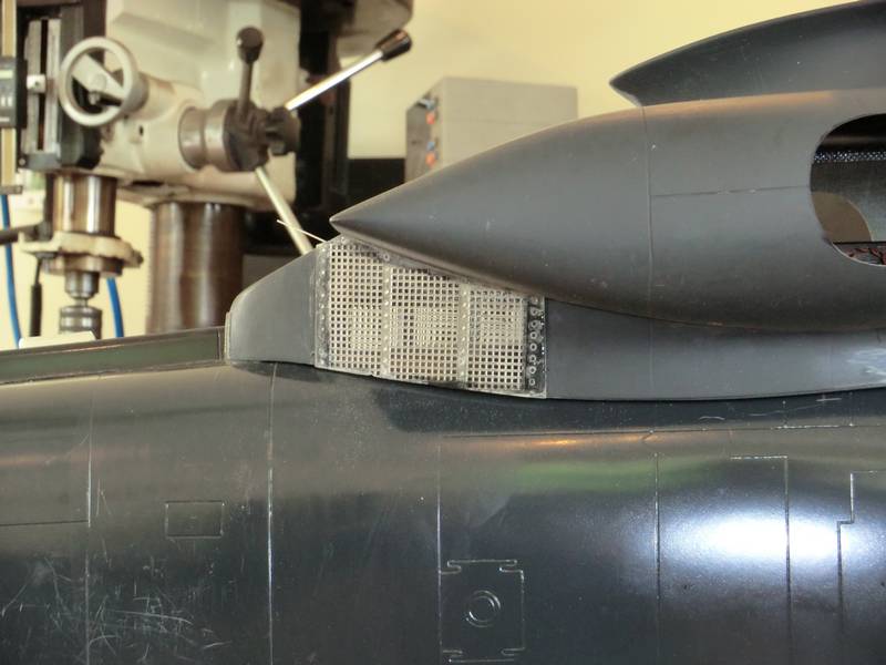
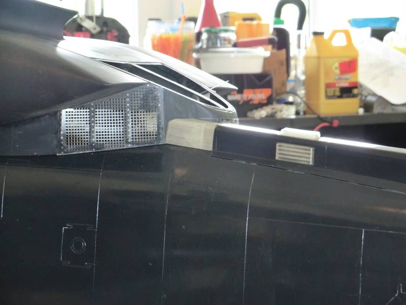
The final part of this assembly was gluing the transmission tunnel down with the mesh vent in place by the fin.
The problem was that the mesh raised the cover off the fin and tailboom so some judicious sanding was needed together with minimum mech. Its worked!
The trick to gluing the tunnel to the fuselage, as it did not fit perfectly, was supplied by Darrell Sprayberry. He suggested holding it in place with packing tape. Very strong and glue would not stick to it. So I first taped it in please with packing tape, then cut around the tunnel and peeled the tape off the tunnel. This gave me a perfect marker to align the tunnel. Then I spread epoxy over the tunnel flanges and retaped the tunnel in place. The excess glue squeezed out onto the packing tape first laid down so it was an excellent mask as well. I took it all off when the glue was pretty rubbery and trimmed any excess off with a knife before it set hard. There wasn't much to do so it worked pretty well.
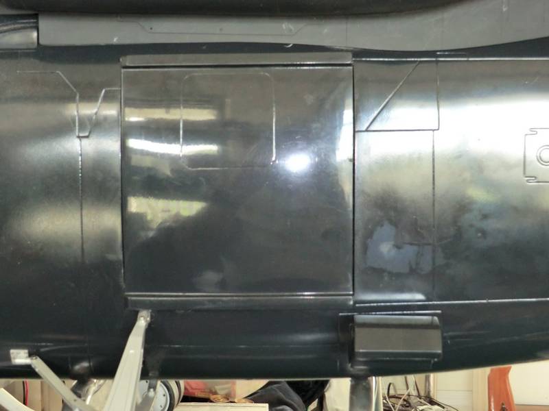
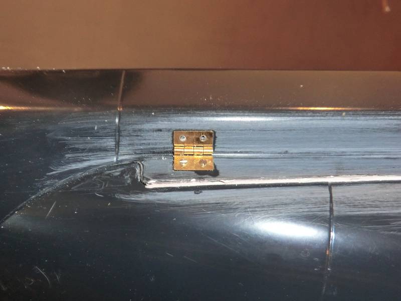
The right hand side of the tunnel did not sit flat and would not bend under the pressure of the tape. This left a small gap of about 1mm so I filled it in with bondo. That's the white line. The next job was to add hinges to simulate the hinges which would allow the tunnel inspection panels to be opened
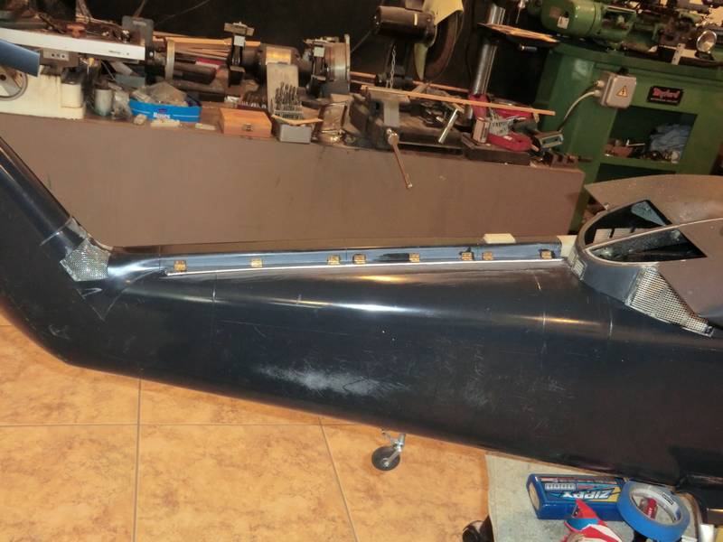
I have drilled all the holes out for micro screws but only fitted a couple to see how they look. If I fit them all when I come to paint them the screw slot will fill with paint and look wrong so i will fit them after painting.
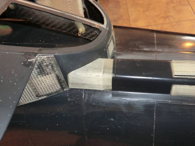
Next the connector to the doghouse that Gavin supplied was the wrong shape. It probably fitted the other doghouse for the 2G model, so I got the printer fired up again and made one up
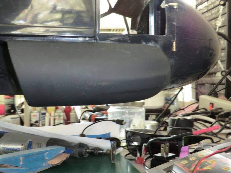
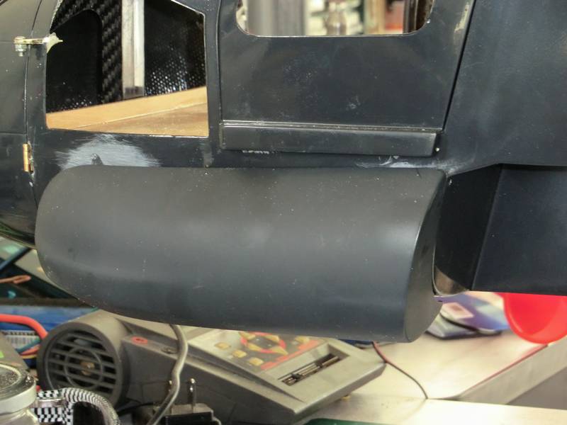
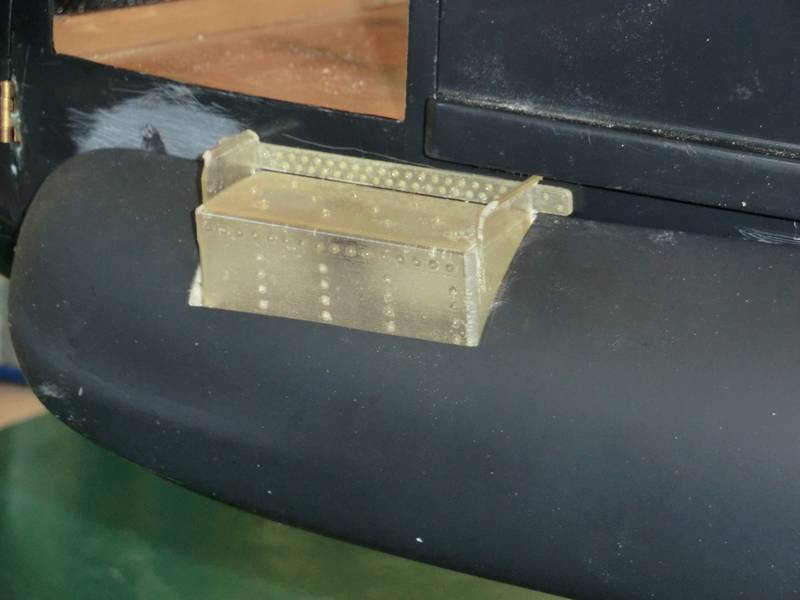
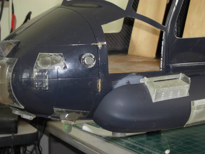
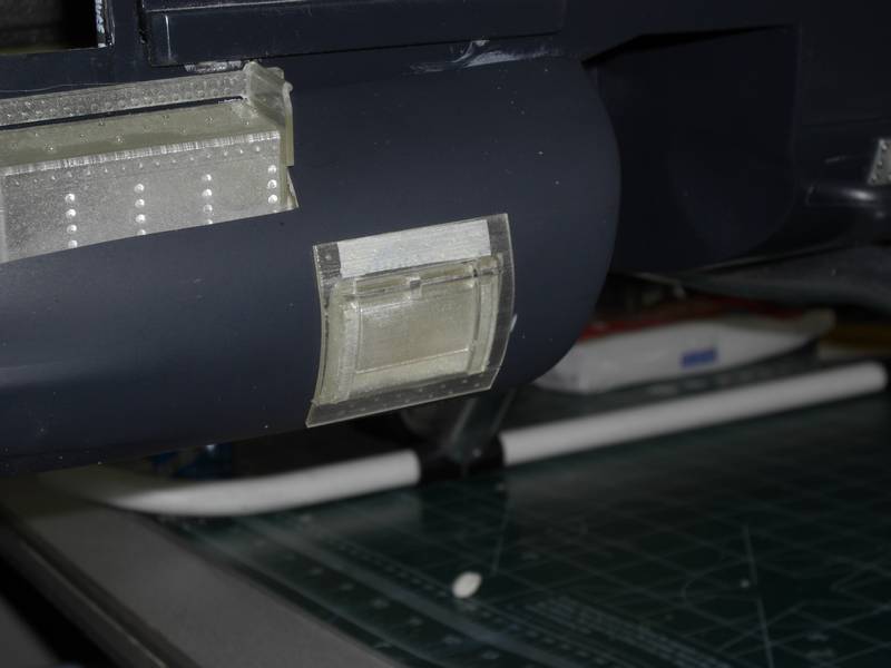
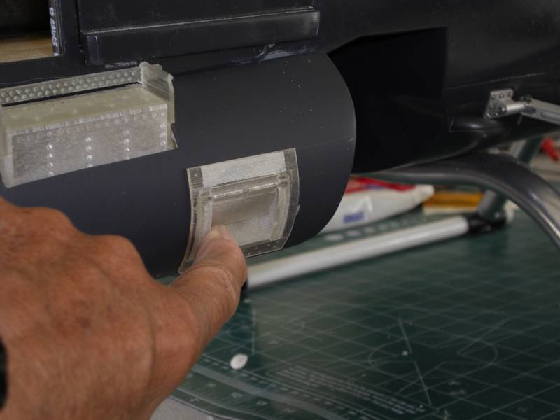
The next task was the flare box in the cabin cheek.
Mounting the fuel tanks gave me some problems but I ended up with a close solution. Now I have to finish scaling the mount.
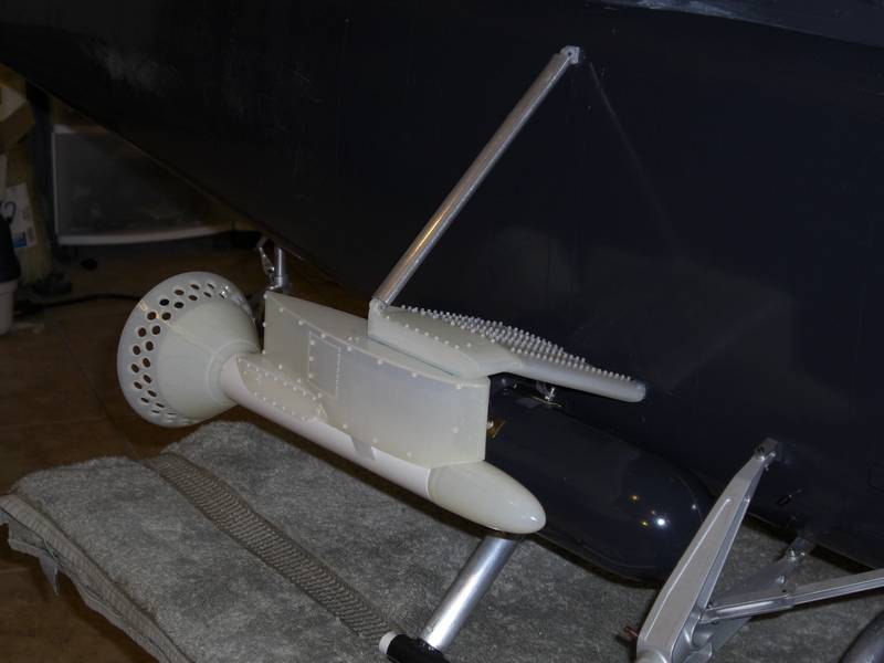
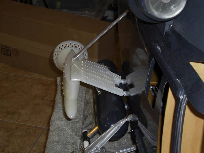
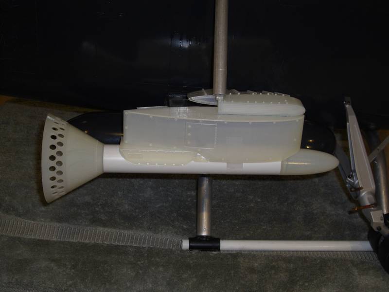
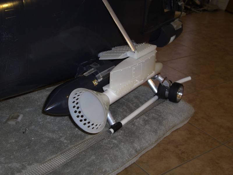
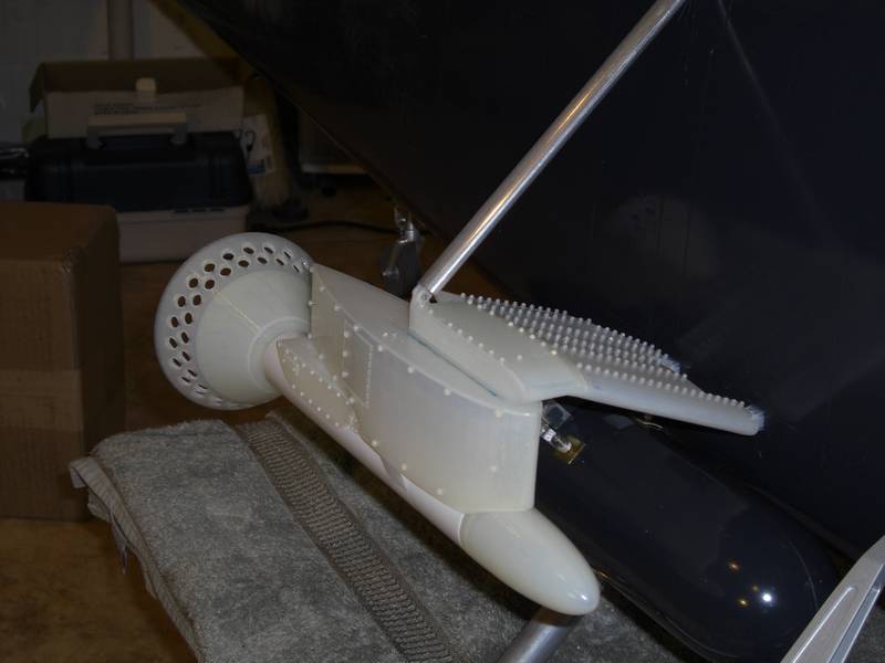
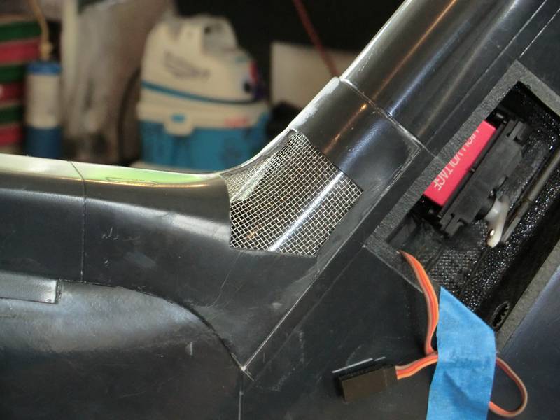
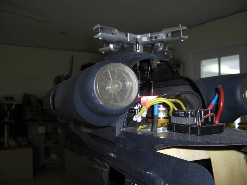
While I was waiting for tank mounts to print I tried my hand at the turbine inlet.
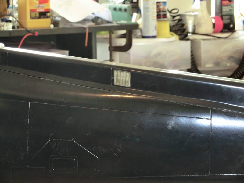
Next came the lighting system. I am going to use ultra bright LEDs driven though power boards from an E-Z Light controller. First job was to mount the lights so I could run the wires. The hardest was the strobe in the cheek, which was still full of foam. It had to be vertical while the surfaces were all at an angle. The tube was printed up and the lens clipped in. The lens wont be permanently fixed until the LED and wires are attached to it.
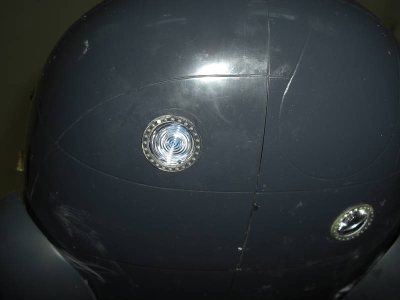
Then the two bezels for the spot lights were mounted over holes cut in the clamshell. The outer rings are fixed but the circular lenses are just taped inside until after painting, then the LEDS will be fitted as well.
The last picture is of the rear strobe mounted to the top of the fin. I have other lights ready to go on, but they cant be fitted until after painting so I wont show them just now, but I will say that designing the internal structure of the nav light assembly was a challenge which I enjoyed.
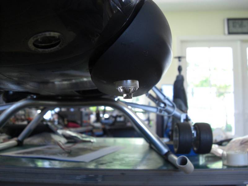
Next came the drop down landing light. Right now, drop down is what it does, I will have to decide whether to make it work or fix it in position.
I decided to tackle the torpedo next. The 6 blade counter rotating props on a cone gave me a learning curve in solidworks, but have turned out pretty nice
Then it was a case of mounting it in its holder with some magnets and fitting the stabilizer screws to it. The idea is to be able to take it off for painting and then I will put a blob of PFM on the magnet when it goes back in place. This will keep it in place but if I bump it or need to get it off the PFM should release without breaking anything.
A few more lumps on the clamshell doors. A lot of work and not a lot to show for it, but I sure am learning how to work with curved surfaces in solidworks.
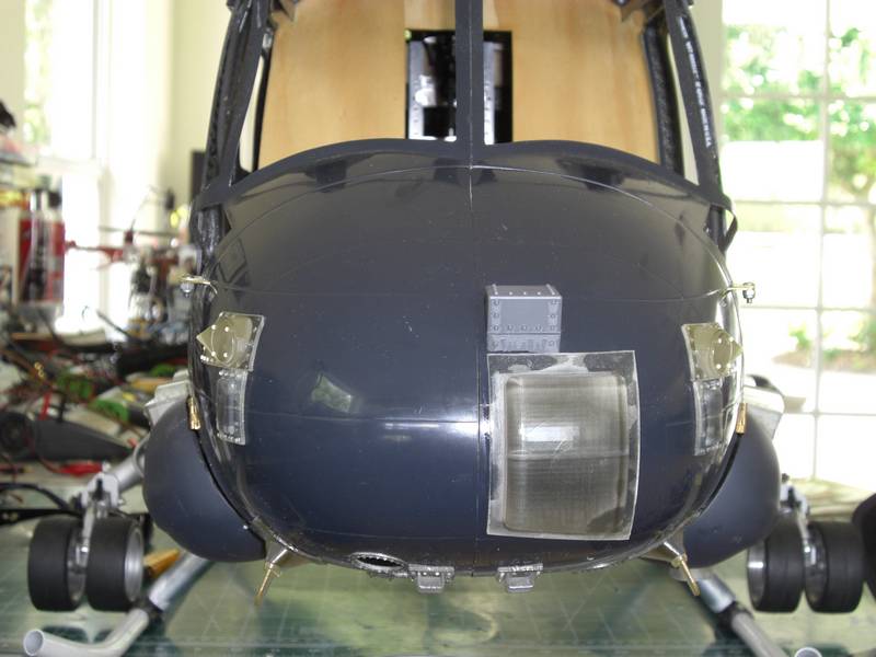
I decided to redesign the triangular piece above the big lump on the front and added rivets to it. When I printed it, the angles forced build material to go under the rivets and make a mark. I gave it a quick squirt of primer to see how it looked and when its painted, probably no one would notice....but I know it doesn't look nice, so I am reprinting it without rivets and will add them later. I have printed the bottom antenna mounts and the blade antennas, but they will be white so they are temporarily attached with double sided sticky tape.
I keep finding more details on these clamshell doors. The latest is the two circular vents.
I also printed up the steps which go in the side cheeks. It was fun making them work, but it made me fit them with doubles sided sticky tape as they will have to come out and apart to be painted
2 weeks work on the 3D printer and with screen measuring gadgets on my other computer finally got me somewhere close to the correct design for the sonobuoy mount. This will be a nice way to end this chapter so here are a bunch of pictures of my work.