After a year working on the Starwood Electric Lama, and the Goblin mechanics for East Coast Scale helicopters, it is now time for me to get back into making something for myself. a New Zealand guy called Gavin proposed to create a 1/6 scale model of the Sea Sprite and put some of his work up on scale RC helicopters. I had seen his previous model and was very impressed by it. The workmanship was outstanding. Gavin makes detailed molds, and from them he pulls a very small number of fuselages, so his work is exclusive and appropriately priced. However his Wessex was just a little too small for me being 600 size. When he announced the Sea Sprite, it was going to be 1/6 scale and that was just the right size. So I placed an order and waited patiently. As his development work approach completion I announced that I would be receiving one of these models and showed pictures of the color scheme that I intended to use. Gavin then told me that the machine I had picked to model was not the version he was making. He was making a 2G version and I had the elected to make a 2F version. There are significant differences between the two models but Gavin offered to make a one-off version of the 2F. He estimated it would take about three months to do and this unique model would command a commensurate price.
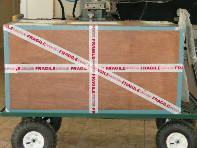
Gavin finish the model on time, and after a little hassle over shipping methods, it was shipped out DHL and arrived the next day! This is what I received.
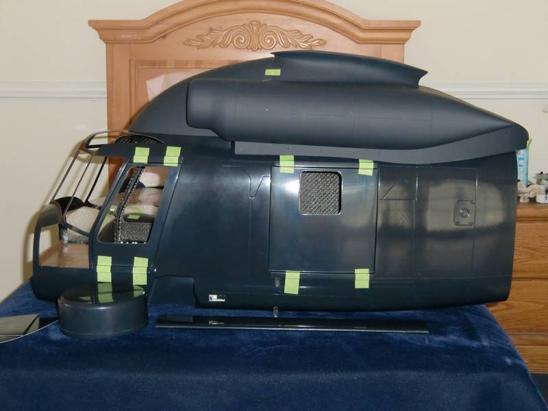
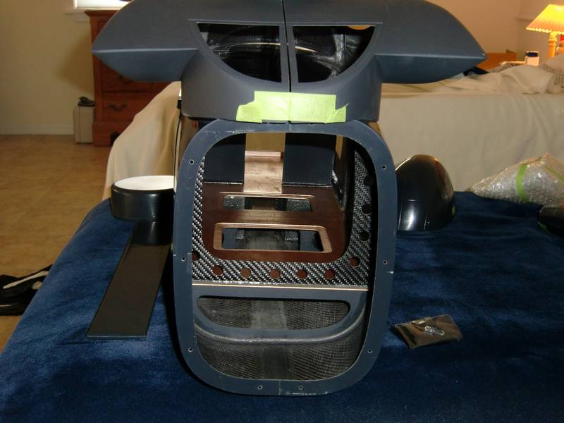
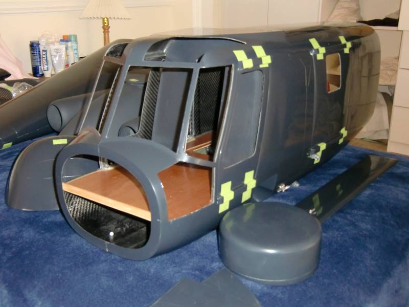
The way this was packaged was indicative of the quality of all of Gavin's work, and I looked forward to opening the box. But when I did, I was not happy! He had used individual polystyrene balls which were heavily static charged, flew everywhere except into the garbage bag and were in every part of the kit. It took 10 minutes to open the box, two hours to get the parts out of the box and cleanup the polystyrene balls, and another two hours to unwrap all of the parts and get rid of all of the polystyrene balls that they deposited all over my house. However, the effort was worthwhile. The parts were in perfect condition, were of exceptional quality and I am absolutely delighted with what I have received. Over the past few weeks I have been ordering the extras I need, like a rotor head, tail rotor gearbox, and other essentials. The one decision I have not yet made is whether to use a turbine, or the Goblin system that I have developed and have a Goblin 770 flying ready to put the four blade head on. Until I can clear the decks, and make space in the workshop for a new project, and the parts I have ordered actually arrive, I have put all of the parts on my wife's bed where they will be comfortable, and I can admire them. There is a lots of plotting and planning to do in the assembly of this model, and I am really looking forward to the build. Here's some pictures of what I have so far.
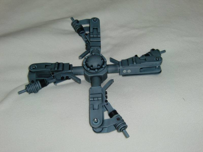
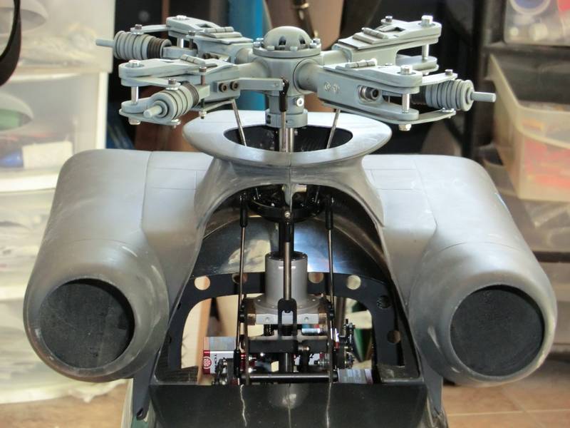
This morning the FedEx guy stopped by and dropped off a big box containing the rotor head from heli classics. Although this is a beautiful scale rotor head it is not scale to this model, but I doubt if any scale rotor head could ever be made scale to this model. I am told that the full size machine has no swash plate. The control rods come out through the main shaft and through a series of bell cranks and cables, operate flaps on the main blades. The main blades do not alter their pitch, the flaps do. This is a picture of the rotor head, and I feel it is crying out to sit on top of a turbine.
well I have come to the conclusion that a turbine is a must. I have two turbine sitting on my bench. One is a jakadofsky, the other a Pahl. The jakadofsky is in a set of mechanics which are of normal configuration in that the exhausts and the tail drive come out of the same end. It has wide splayed legs which will mean a large hole being cut in the top of the fuselage to get the mechanics in. The Pahl mechanics are much narrower and have the exhaust at one end and the tail drive at the other end. This means putting the mechanics in so that the exhaust faces forwards. I contacted Zimmermann and they offer a selection of exhausts designed to go on to both turbines and you purchase curves and straights to make up and exhaust to suit your particular installation. The Pahl turbine mechanics is a good option. However politics, dictate I should use a jakadofsky so I have ordered a pro 5000 from Joe Howard. The M blades have arrived. 855 mm long, 65 mm width. I intend to run them between 1100 and 1200 RPM.
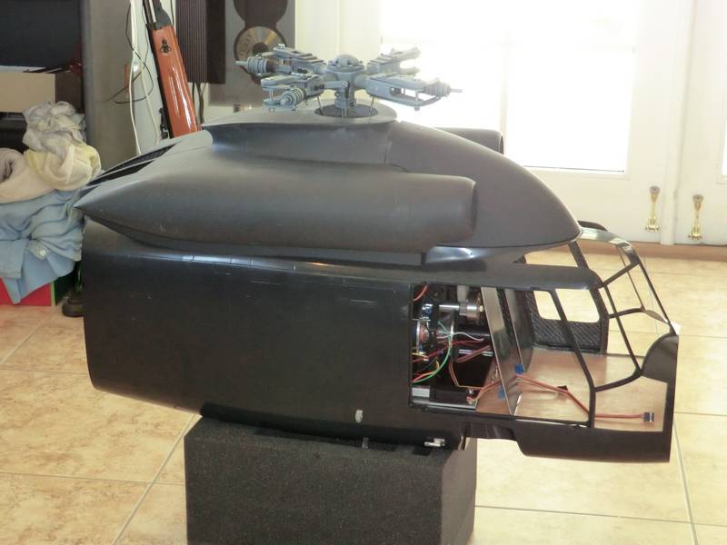
So, the first thing to do is a job I have been putting off and that is cutting a large hole in the top of the main fuselage.This morning I finally bit the bullet and cut a hole large enough to accept the Pahl mechanics. Then I had to cut a small circular hole in the doghouse where the main shaft would protrude through. I had previously tried fitting the rotor head to the main shaft in the hope that the bolt holes would line up. No such luck! I then thought of cutting the main shaft down rather than redrilling a hole as drilling a hole in a hardened shaft is not easy. However,I have put it off, fortunately ! This is the reason why
The top of the main shaft is level with the top of the doghouse so I will have to build a platform to support the turbine so that the rotor head is level with the tail rotor.This will mean temporarily fitting the tail boom and using a laser to find out the height above the doghouse that the center of the rotor head should be. Then I will know how high to build the platform.
further investigation showed that it is not too important to get the rotor head and the tail rotor at exactly the same height. So I set to work on sorting out the turbine. A shiny new Jakadofsky Pro 5000 arrived from Joe so I took the Pahl out and tried to fit the 5000 in. Instantly it was obviously not going to fit! The problem was the first drive gear in the mechanics was much larger than on the old Jakadofsky mechanics and this prevented the turbine from being mounted high enough up.
so I reassembled the Pahl mechanics and refitted the gear to the jakadofsky mechanics, and then fitted the new turbine in place of the old jakadofsky. Then I had to increase the size of the hole I had cut in the top of the fuselage by 2 inches and new mechanics dropped in nicely. Then I looked at mounting the rotor head on top of the existing main shaft and found that if I raised the mechanics by 45 mm everything would fit.... Except the tail rotor output was right at the top of the fuselage.
Having done all that the next job was to make a baseplate to mount the mechanics on. I had intended to use quarter-inch ply then I changed my mind and cut up a carbon fiber plate and made it fit. This plate has straight fibers rather than the woven pattern that is usually a feature of carbon fiber, in the woven version there is more resin than carbon. With straight fibers, there is very little resin and the carbon fiber sheet is absolutely rigid. It is heavier than the woven version and much, much harder. So, three hours later, I have a new floor which is only 2.5 mm higher than the existing floor.
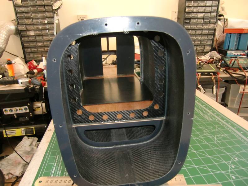
The next part is a bit painful. The only place I can put fuel tanks is underneath the floor. The holes that Gavin had already made in the floor were not big enough to allow me to get fuel tanks in so I had to open them up. I also needed to open them up even further to clear the wooden blocks which were underneath the carbon fiber plate and held the blind nuts which fixed the turbine in place. So, it was out with the trusty dremel, and the cutting disc, and I set to work. I purchased some 32 ounce tanks but found that they were too high to fit around the corner of the fuselage. My calculations showed I needed a minimum of 60 ounces which would give me 10 minutes flying time at full power. This should give me 15 minutes or more cruising around. So I purchased two 24 ounce tanks and a 14 ounce tank. They fitted well but then I found an 18 ounce vario tank lying around and thought I would use that as I could get it in sideways. This is how they all fit in place, but, there will be foam padding around all of the tanks to minimize any foaming due to vibration.
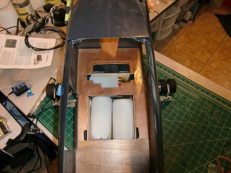
The carbon plate fits over the tanks as before, but I intend to fix this plates in place with epoxy. This was a difficult decision as it means I will have no access to these tanks once the plate is glued in place so I've glued some wooden guides for the rear tanks and I will be able to pull them back towards the tail boom and access the connections from the rear. The front tank will be a problem if something goes wrong! The only access route will be by cutting a hole in the carbon fiber. I drilled the mounting holes for the turbine after carefully centering it up, and then I glued some wooden blocks under the holes and fixed some blind nuts in place with some hy sol epoxy.
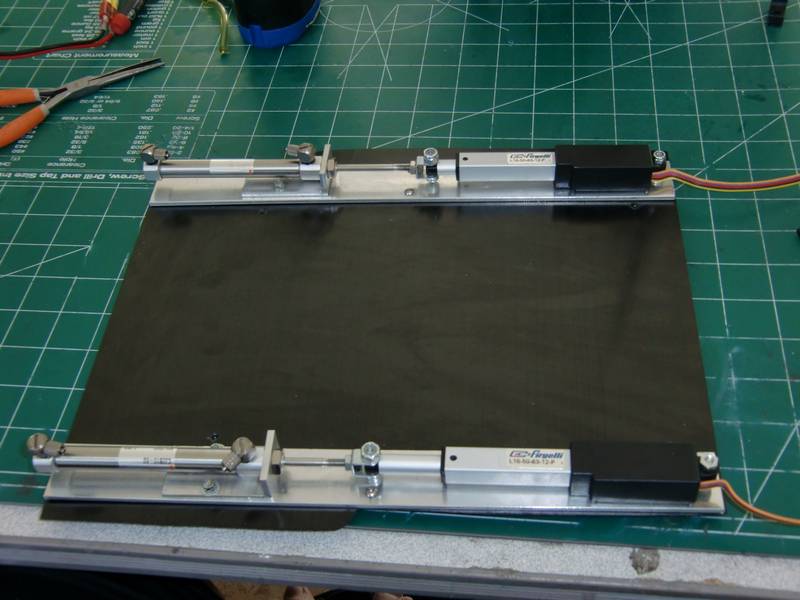
Before I finally fix the carbon plate in place, I want to make up two mounting plates for the hydraulic system which operates the landing gear. The only place I have room for these is on either side the turbine. I want to have these working and mounted before I glue the plate in place. So I spent a happy couple of hours playing with oil, cylinders, rams and linear actuators. There is no bleed system so filling the entire system up with oil and removing all their took a little patience. In the end I managed to get everything working and then proceeded to mount a cylinders and the actuators on a piece of aluminum and then drill and tap the carbon fiber plate so that I could mount them either side of the turbine.
A little later on I will look for some connectors which are scale and allow me to feed the pipes out through the side of the fuselage in the correct place. But that can wait for a while. Now the plate is sitting inside the fuselage on top of a lot of epoxy resin and while it sets I am thinking, what did I forget to do? It's too late now!
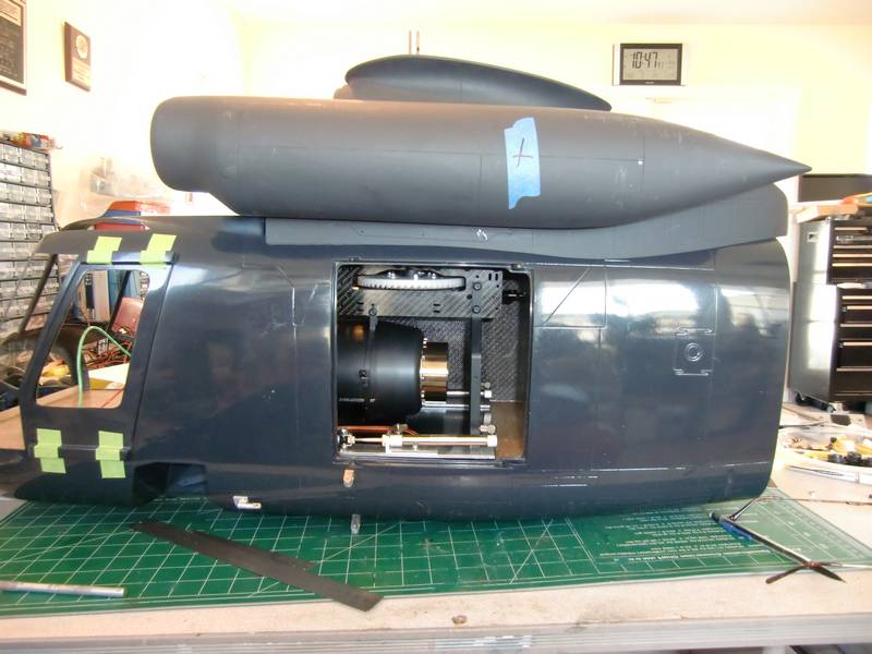
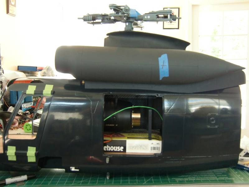
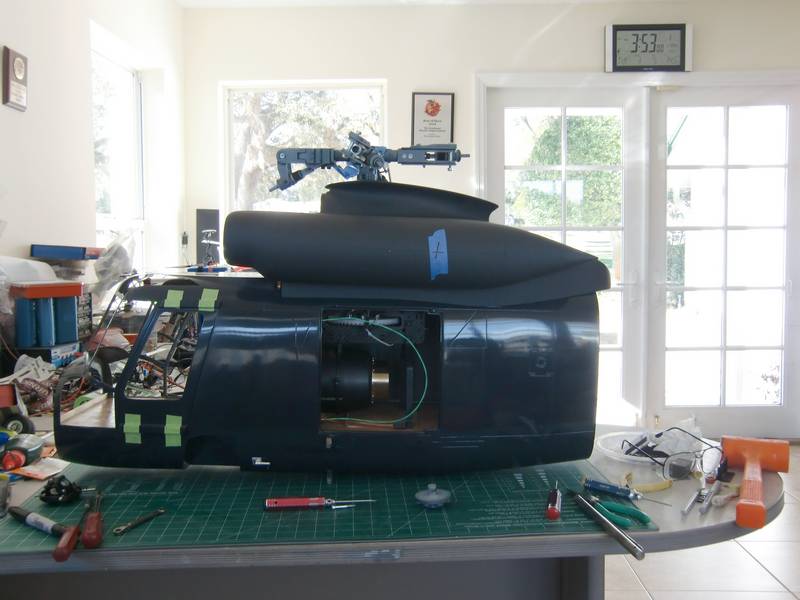
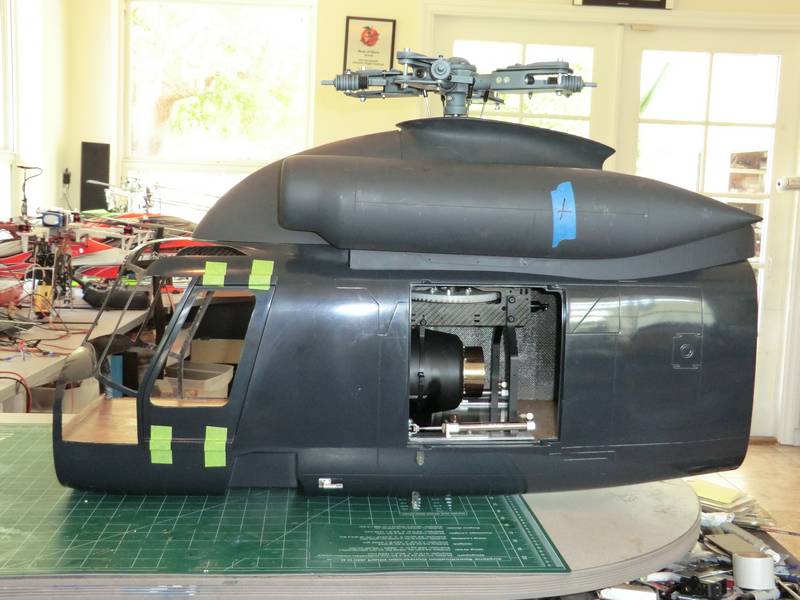
Thats how it goes together, now all I have to do is to figure out the exhaust system. I have ordered some parts from Zimmermann in Germany as they make a selection of bends and straights you can use to make your own system. When they arrive I will see whats involved in getting the turbine output to the scale exhaust position where the blue tape is on the doghouse
Meanwhile while I was waiting for these parts to arrive, I decided to fit the servos and make up pushrods. I wanted extra support for the main shaft so I bought a vario dome which increased the bearing height by another 2 inches. It needed a couple of 6mm spacers to get the dome to be the same width as the frames and fortunately I found some 6mm x 12mm rod lying around. That made it a quick job. The problem was that there is no anti-rotation bracket, anti-rotation is performed by the servos fore and aft which have A arms from their linkage. These are now 2 inches too short so I had to make up an extension and they needed it to be rigid so that the anti-rotation feature was retained. As I will not be doing 3D, I decided that a steel rod, although heavy, would be the best solution. Aluminum would have a constant bending force on the screw threads and eventually would fail. Then it was a simple job of making up new pushrods. However I did decide to change the ball links everywhere around the swash plate to rocket city 6 mm ball links which already had a 3 mm diameter hole through the ball and had to be screwed in place. These are very smooth and very difficult to get apart so I do not anticipate them coming apart in-flight.
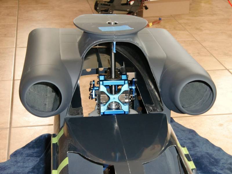
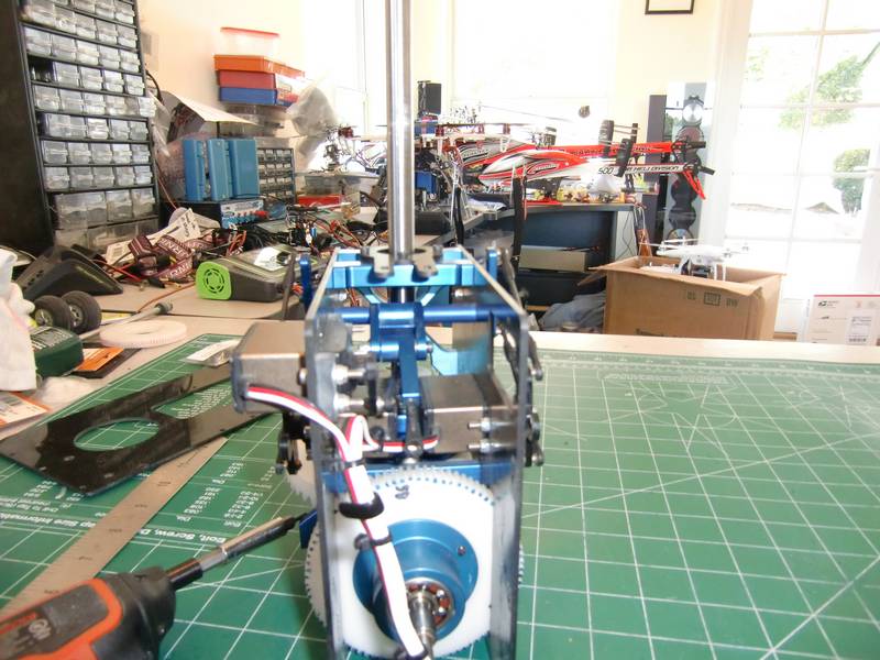
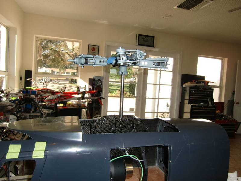
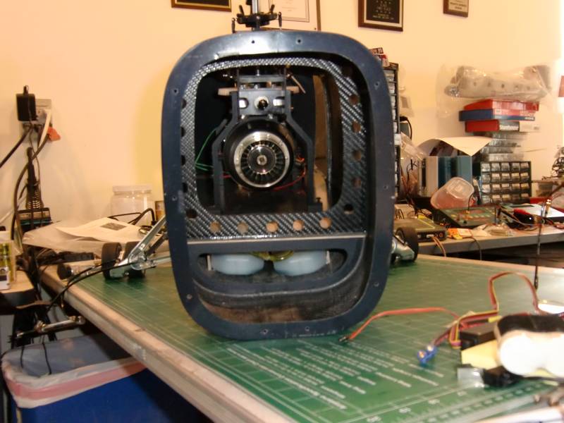
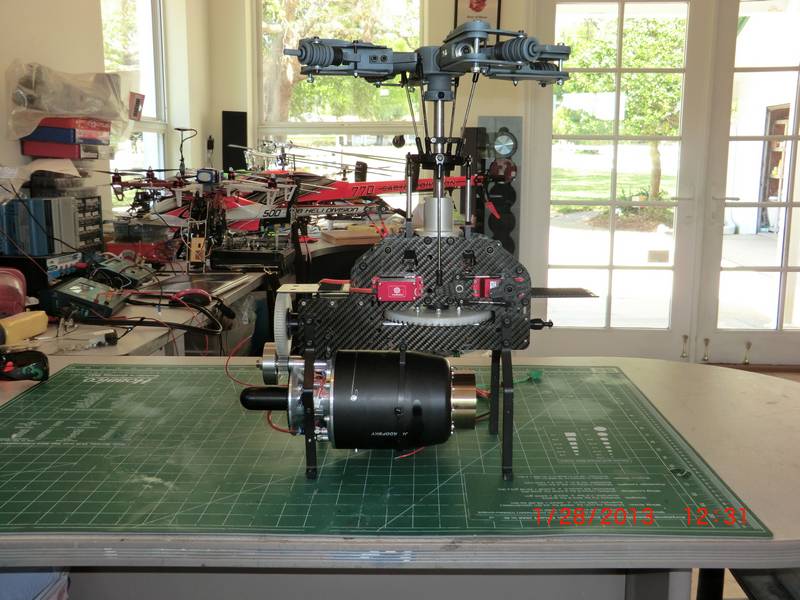
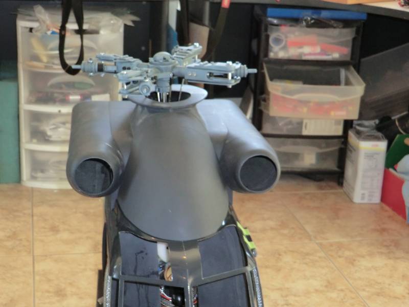
This is what it looks like so far
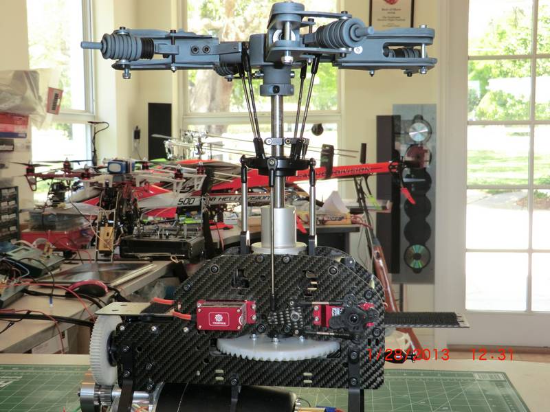
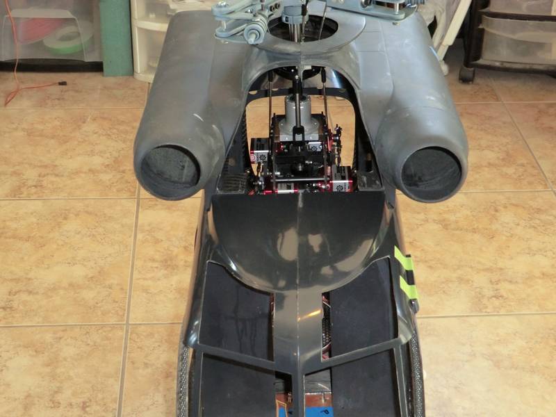
And a closer view
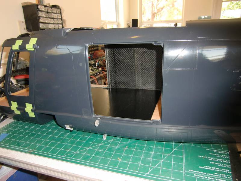
An intermediate step is the fitting of the upper doghouse. I had to draw a circle on the top of the doghouse and then cut it to fit. I knew I would find a use for one of the V bar CD ROMs eventually. It was exactly the right size
The front section is detachable and will be held in place with magnets. The two half's of the doghouse are pinned held in place with magnets and this is already done
The flat surface underneath the front section seems to me to be a prime position for all of the electronics and maybe all of the turbine components. It will certainly make access very easy if I have to adjust anything, simply pull the front off. More thought required on that one
I spent most of the weekend gluing magnets to the doghouse and to the main fuselage. The problem is that due to the turbine exhausts coming out on the side of the nacelles, I am prevented from simply pulling the doghouse straight up. It has to come off sideways to clear the exhausts. This has required the use of a lot of large magnets and the two halves are pinned to line up with each other. The front dome will also have some magnets glued onto it this afternoon and tomorrow I will glue magnets inside the fuselage to locate it.
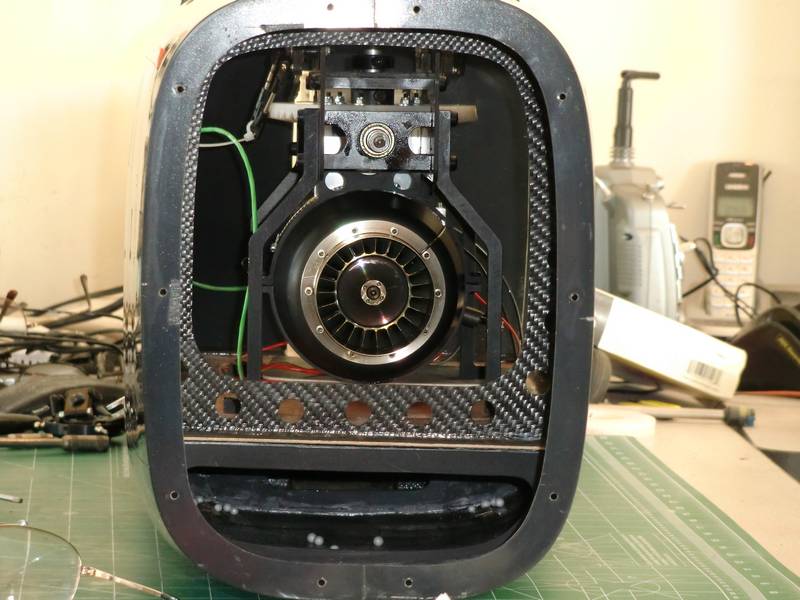
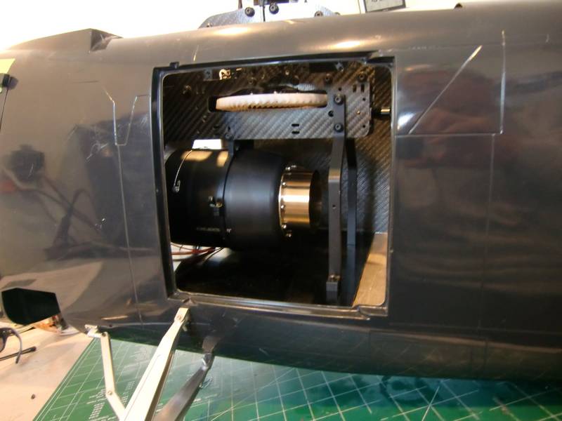
This side of the installation looks very clean, but I don't have the exhaust yet. The other side is somewhat more congested.
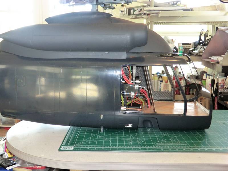
I did make the mistake of zip tying all of the wires together in one big neat bundle, but then I realized I would not be able to get the turbine out of the fuselage. So all of the individual wiring had to be zip tied so that it would be possible to disconnect everything and remove the turbine comparatively easily.
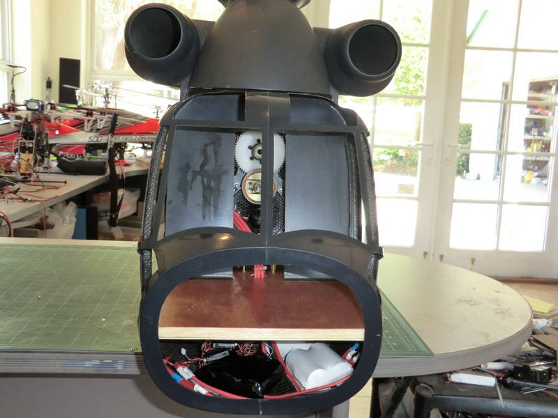
I have decided to use two A123 packs for the receiver and the turbine comes with its own lithium-ion battery. All these will be mounted underneath the floor of the cabin. Hopefully I will be able to make the front to doors hinged so that I can access the connectors easily. it looks nice like that doesn't it?
Here is the real horror story. The Jakadofsky control ECU is very large and so has to be mounted on Velcro so as to space it up high enough that the dome will slide underneath it. The other parts have only been loosely fitted in there for the time being until I got everything working properly. Not a wiring job to be proud of I am sure!
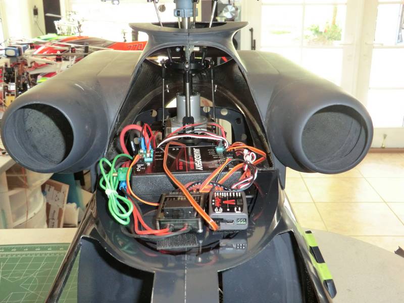
The next job is to install a GY 611 Gyro for the tail and try and find somewhere to put that. At the same time I will probably make a bit more of an effort to tidy up all this wiring. It is the exhaust system that is holding me back now.